2. CONNECTING
IMSRM04-E8
11
2.3 Connection Between the Operation Panel and a Host
Computer
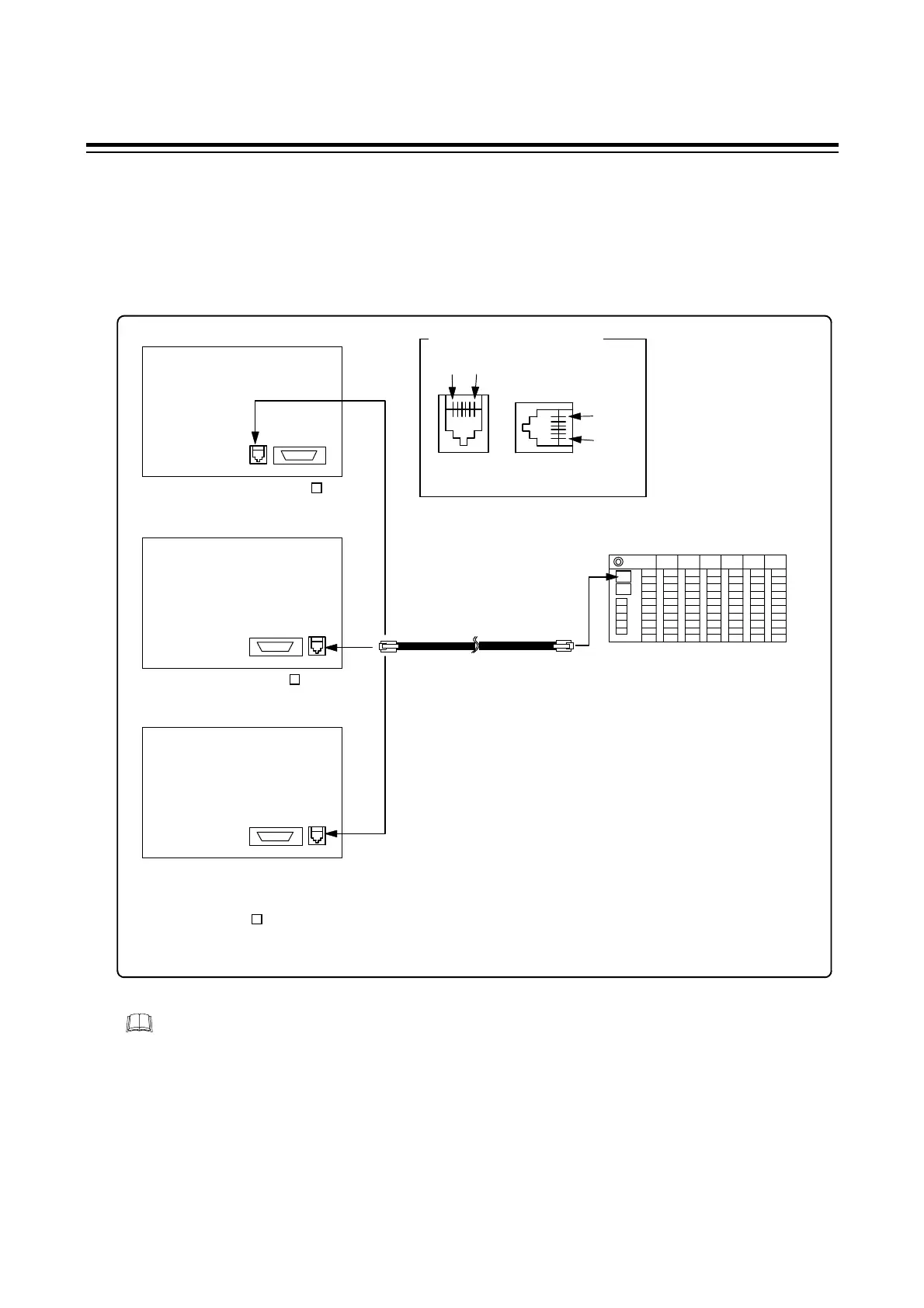
2.3.1 OPL or OPL [CE/UL/CSA Conformed] connection
Connect to the modular connector on
the oparation panel [COM.PORT].
Connect to the modular connector
on the PCP module [COM.PORT1].
Control unit
100 to 240 V AC [OPL-A
∗
]
24 V DC [OPL-A
∗
]
CE/UL/CSA Conformed
100 to 240 V AC,
24 V DC
[OPL-A
∗
/CE]
Modular cable pin numbers
Control
unit
Operation
panel
1
to
6
1 to 6
RKC special cable type : W-BF-02-3000 (Sold separately)
[Standard cable length: 3m]
The cable type partially differs depending
on the cable length when ordering.
For the CE/UL/CSA approved instrument, install the ferrite cores attached to the operation
panel to both ends of the cable.
 Loading...