2. CONNECTING
IMSRM04-E8
12
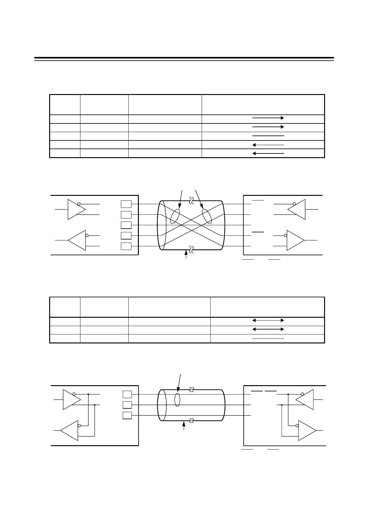
RS-422A
Pin number and signal name
Pin No. Mark Name
Signal Direction
Operation panel Host computer
2 T(A) Send data
6 T(B) Send data
5 SG Ground for signal
4 R(A) Receive data
8 R(B) Receive data
Contents of communication cable wiring
RS-485
Pin number and signal name
Pin No. Mark Name
Signal Direction
Operation panel Host computer
2 T/R(A) Send data/Receive data
6 T/R(B) Send data/Receive data
5 SG Ground for signal
Contents of communication cable wiring
2
6
5
Shielded twisted
pair wire
(Maximum connections: 16 units)
TXD and RXD : negative logic.
TXR/RXD
TXR/RXD
SG
T/R (A)
T/R (B)
SG
Paired wire
Host computer
Operation panel
2
6
5
4
8
Shielded twisted
pair wire
(Maximum connections: 16 units)
Paired wire
Host computer
T (A)
T (B)
SG
R (A)
R (B)
TXD
TXD
SG
RXD
RXD
Operation panel
TXD and RXD : negative logic.
 Loading...