3. SETTING FOR COMMUNICATION
IMSRM04-E8
21
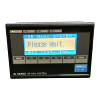
2. Set the desired data configuration and communication speed by the dip switches located in the
PCP module.
Upper section
View from the rear with the
mother block removed.
1
2
3
4
ON
OFF
1 2 Data configuration 3 4 Communication speed
OFF OFF 8-bit non parity OFF OFF 2400 bps
OFF ON 7-bit even parity OFF ON 4800 bps
ON OFF 7-bit odd parity ON OFF 9600 bps
ON ON (Don't set this one) ON ON 19200 bps
3. After completing the setting, engage the upper connection of the mainframe with that of the
mother block, then perform the reverse order of separation to engage the lower part of the
mainframe with the mother block with the upper connection set to the fulcrum. Firmly engage
the mainframe with the mother block until a click sound is produced.
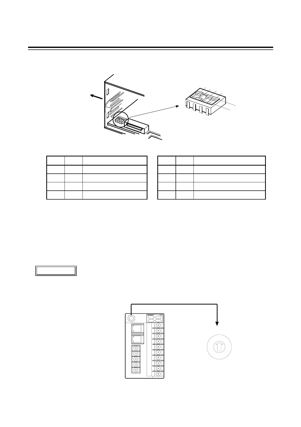
Unit address setting
Set the unit address so that its setting is different from other address settings on the same
line. Otherwise, problems or malfunction may result.
8
7
6
5
4
3
2
1
0
F
E
D
C
B
A
9
PCP module
Setting range: 0 to F (hexadecimal)
Addresses 0 to 15
Unit address setting switch
CAUTION
Setting procedure:
Set the address by the PCP
module unit address setting
switch on each control unit.
For this setting, use a small
slotted screwdriver.
 Loading...