IMR01M01-E16
3
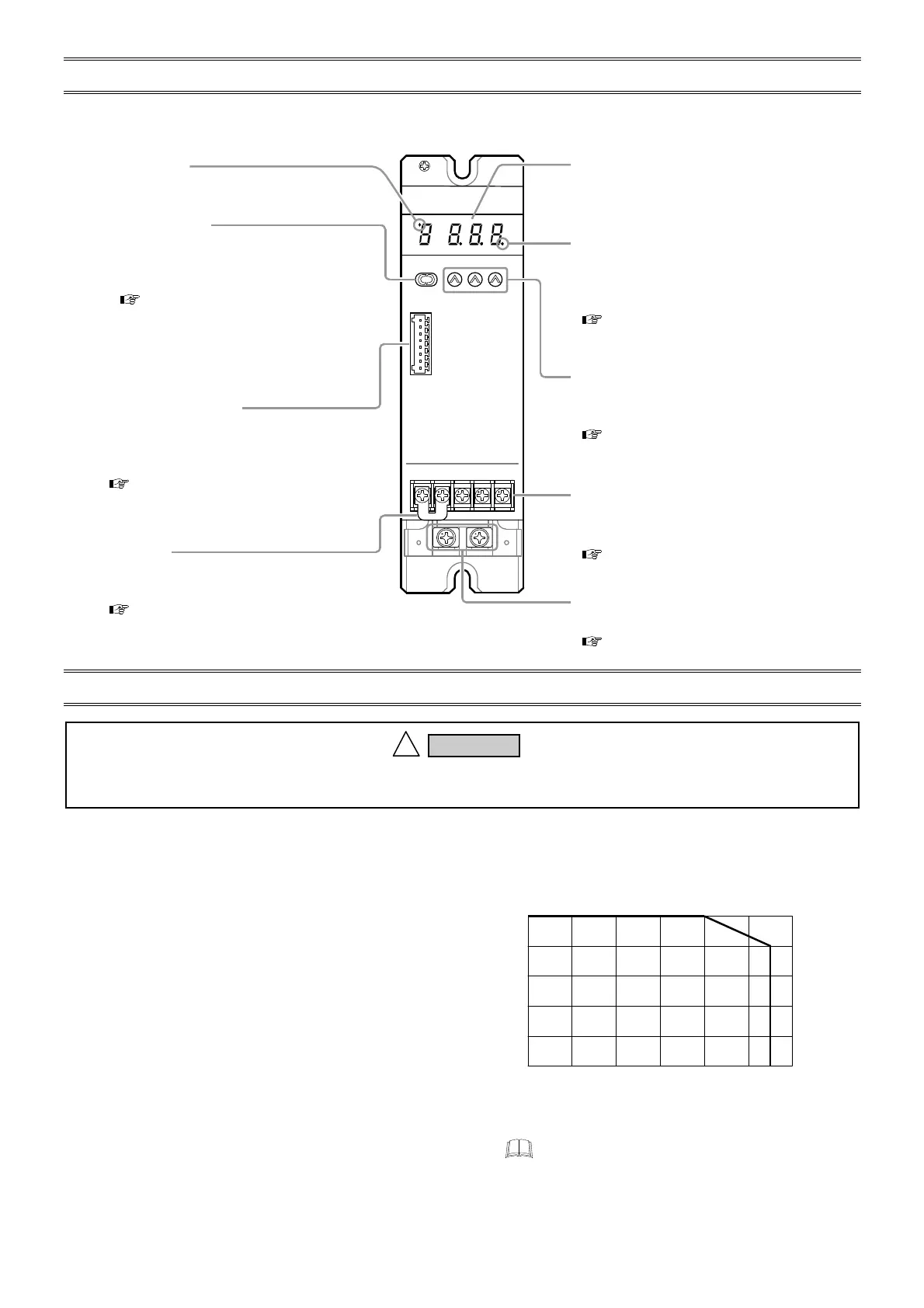
3. PARTS DESCRIPTION
The 20 A and 30 A types are used in the following figures for explanation, but the same explanations also apply to 45 A, 60 A,
80 A and 100 A types.
4. MOUNTING
4.1 Mounting Environment
Avoid the following conditions when selecting the mounting location:
• Ambient temperature of less than 0 °C or more than 40 °C.
(The rated current drops when the ambient temperature exceeds 40 °C.)
The temperature inside the control panel increases due to heat
generation of this instrument itself. Therefore, take into account
full ventilation by mounting forced ventilation fans on the panel.
• Ambient humidity of less than 5 % or more than 95 %RH.
• Rapid changes in ambient temperature which may cause
condensation.
• Corrosive or inflammable gases.
• Direct vibration or shock to the mainframe.
• Water, oil, chemicals, vapor or steam splashes.
• Excessive dust, salt or iron particles.
• Excessive induction noise, static electricity, magnetic fields or
noise.
• Exposure to direct sunlight.
• Excessive heat accumulation.
To prevent electric shock or instrument failure, always turn off the power before mounting or removing the
instrument.
!
WARNING
0
20
40
60
80
100
10 20 30 40 50 55
Load
current (%)
Temperature characteristic
(Including the closely mounted)
60
Temperature (
°
C)
The temperature characteristic is common to the all
types (20 A, 30 A, 45 A, 60 A, 80 A and 100 A).
Power lamp
Lights when the power is turned on.
Connector (socket)
Connect with a setter (potentiometer), external
contact or controller. In addition, used to heate
break alarm output.
( P. 9)
Display
Display the input signal values and
parameters.
Parameter key
• Select the desired parameter group or to
call up the desired parameter.
• Switch the Setting data lock function.
( P. 11, P. 12)
Set data lock lamp
Set data lock lamp will be lit when key
operation is prohibited.
[Set data lock function]
( P. 12, P. 23)
UP keys
• Change the values.
• Switch the Setting data lock function.
( P. 12)
Input and power supply terminals
Connect input signal and power supply
wires.
( P. 7)
Main circuit terminals
Connect main circuit wires.
( P. 7)
Short bar
Switch input types: voltage input, voltage
pulse input or current input.
( P. 8)

 Loading...


