IMR01M01-E16
11
6. SETTING
This chapter describes the display menus on the LED display.
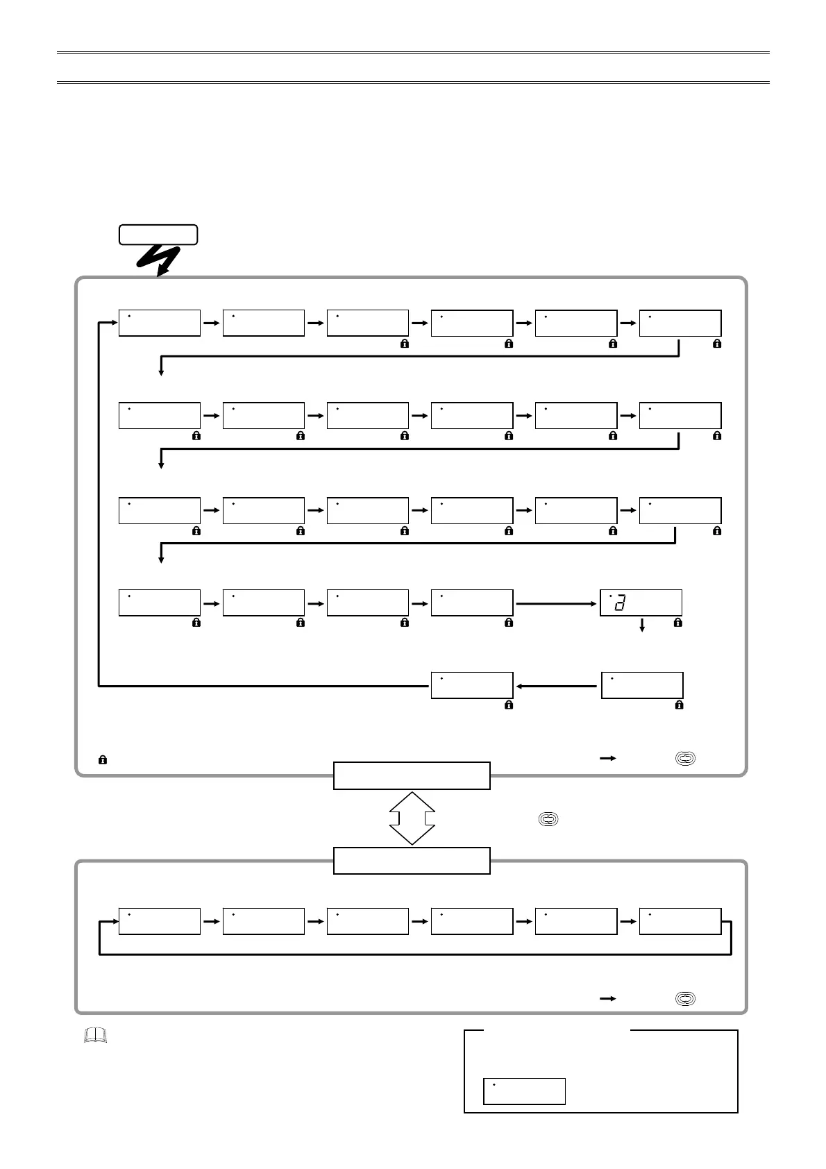
6.1 Display Flowchart for Monitor and Setting Parameters
The instrument has two Monitor/Setting modes.
• Parameter group 1 includes parameters for both monitoring and setting such as Input signal monitor 1, Phase angle
monitor, Phase/Zero-cross control selection, and others.
• Parameter group 2 includes parameters for monitoring such as Power frequency monitor, Input signal monitor 2, and
others.
fter the maximum load current value is displayed on the display, the display will automatically
change to the Input signal monitor 1. (Display for approx. 1 second)
Input signal
monitor 1
Phase angle
ratio monitor
Control method
Soft-start time
Soft-down time
Internal gradient
set value
Output limiter
(low)
Output limiter
(high)
Base-up
set value
Output mode
for phase control
Internal manual
set value
Contact input
action
Maximum load current
set value for alarm
1
Heater break
alarm 1 set value
setting
1
Number of alarm
delay times
1
Heater break
alarm type
1
Alarm output
selection
1
Heater break alarm 2
set value setting
1
Heater break alarm 2
used/unused
1
Current limit value
setting
1, 2
Alarm output
state selection
1
: Press the key.
8.8.8.0. M.8.8.0
.
C.8.8.0
.
U.8.0.1
.
D.8.0.1. G.1.0.0.
H.9.9.9
.
L.8.0.0. B.8.0.0. O.8.8.2. I.8.0.0. J.8.8.0
.
P.3.0.0. Q.8.2.0
.
R.8.3.0. N.8.8.0. T.8.8.0. F.8.1.5.
K.8.8.0. Z.3.2.0
.
c.8.8.0.
Power ON
Protection function for
control of primary side
of a transformer
1
Determination set value in case of a
break on the secondary side
of the transformer
1
t.8.8.0. T.8.8.0.
Output limiter setting in case of a
break on the secondary side
of the transformer
1
h.2.0.0. u.8.8.0.
Soft-start time in case of
break on the secondary side
of the transformer
1
1
These parameters are not displayed when the Heater break alarm, Current limiter, Constant current control and Protection
function for control of primary side of a transformer functions are not provided.
2
Factory set value varies depending on the instrument specification.
: Available for the Set data lock function
: Press the key.
Power frequency
monitor
Input signal
monitor 2
External gradient
set value monitor
External manual
set value monitor
Contact input
state monitor
If any error or alarm occurs, the present display
is changed to the error or alarm display.
CT input
*
*
These parameters are not displayed when the Heater break alarm, Current limiter, Constant current control and Protection
function for control of primary side of a transformer functions are not provided.
Parameters other than Input signal monitor 1, Phase angle ratio
monitor and CT input monitor return to Input signal monitor 1 if key
operation for more than one minute is not performed.
Parameter group 1
Parameter group 2
Error display
1.8.8.0. 2.8.8.0. 3.8.8.0. 4.8.8.0. 5.8.8.0. 6.8.8.0
.
E.8.8.2.
Error or alarm display
Press and hold the key for 2 seconds.

 Loading...


