IMR01M01-E16
10
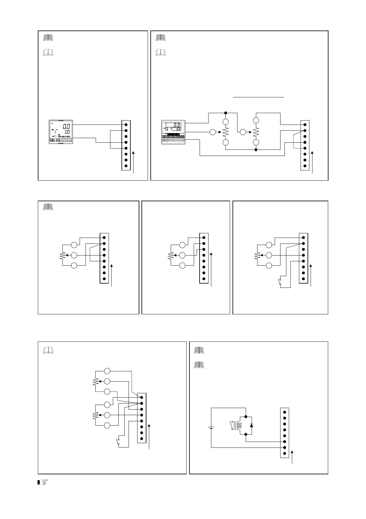
Contact input ON/OFF control
For contact input, short connector
pin No.2 with connector pin No.5.
For ON/OFF control, short connector pin No.2 with connector pin
No.5.
To set or change the output range, set High limit setter first.
The set value of Low limit output value conforms to the value of High
limit setter. The Low limit output value automatically changes when
changing the set value of the High limit setter during the operation with
the set value of the Low limit setter.
Low limit output value = Set value of high limit setter
×
Set value of Low limit setter
Example: Set value of the High limit setter: 80 %
Set value of the Low limit setter: 40 %
80 %
×
40 % = 32 % Low limit output value 32 %
To conduct ON/OFF control, set the
value of the Output limiter high and the
Output limiter low after wiring the
contact input.
Contact closed: Output limiter high
Contact open: Output limiter low
C
NO
C: Common
NO: Normally open
+5 V output
Controller
ON/OFF signal
1
Pin number
2
THV-1 connector
4
5
Short
NC
C
NO: Normally open
NC: Normally closed
C: Common
Controller
ON/OFF signal
NO
Low limit setter High limit setter
1
2
3
1
2
THV-1 connector
4
2
1
3
Pin numbe
Short
5
Auto mode*
Manual mode (With gradient setter) Auto/Manual mode selection *
1
For manual setting, short
connector pin No.2 with
connector pin No.5.
Manual
setter
Short
3
2
1
2
4
5
1
Gradient
setter
3
2
1
2
3
THV-1 connecto
1
Manual
setter
External contact closed: Manual mode
External contact open: Auto mode
3
2
1
2
4
5
THV-1 connecto
THV-1 connecto
Pin numbe
External contact
Pin number Pin number
* For input signal wiring, refer to Current input 4 to 20 mA DC, voltage input 0 to 10 V DC, 1 to 5 V DC and
voltage pulse input 0/12 V DC (P. 8).
Auto/Manual mode selection (With gradient setter) Heater break alarm output
The gradient setting is valid for both Auto mode and
Manual mode.
A diode should be used and connected as
show in the diagram, when using a relay.
When the power is turned on, the Heater
break alarm output may be turned on for up
to 0.5 ms. When an interlock circuit or any
other related circuit is used, take a necessary
measure externally for delaying the
activation of the circuit more than 0.5 ms.
THV-1
connector
1
Manual setter
External contact closed: Manual mode
External contact open: Auto mode
3
2
1
2
4
5
3
2
1
Gradient setter
3
Pin number
External contac
THV-1 connector
6
7
Pin number
Diode
Relay
For input signal wiring, refer to Current input 4 to 20 mA DC, voltage input 0 to 10 V DC, 1 to 5 V DC and
voltage pulse input 0/12 V DC (P. 8).

 Loading...


