IMR01M01-E16
9
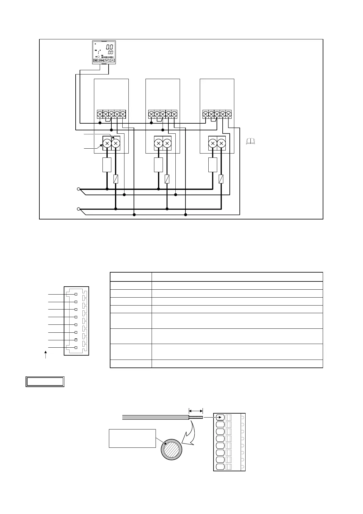
Application: Voltage input 0 to 10 V DC, 1 to 5 V DC or Voltage pulse input 0/12 V DC
(Parallel connection)
THV-1 input impedance
1 to 5 V DC, 0/12 V DC: 30 kΩ
0 to 10 V DC: 68 kΩ
The number of THV-1 that
can be connected depends
on the allowable load
resistance of temperature
controller being used.
For resistance of controller,
refer to specification of the
controller instruction manual.
Temperature controller
0 to 10 V DC
1 to 5 V DC
0/12 V DC
THV-1
Input and power
supply terminals
1 2 3 4 5
+
−
Power supply
100 to 240 V AC
(50/60 Hz)
Main circuit
terminal (2/T1)
Main circuit
terminal (1/L1)
Input and power
supply terminals
1 2 3 4 5
Input and power
supply terminals
1 2 3 4 5
THV-1 THV-1
Fast-blow fuse
Load
Load
Load
5.3 Wiring for connector
The connector is used for Contact input, Auto/Manual mode selection, External gradient setting, Heater break alarm 1 output
or Heater break alarm 2 output. Use the optional connector (plug) for wiring.
Pin number and details
Pin number Details
1 +5 V output
2 0 V
3 Gradient setting input (0 to 5 V input by the gradient setter)
4 External manual mode input (0 to 5 V input by the manual setter)
5 Auto/Manual mode transfer (contact open: auto mode)
Shorting No.2 pin (0 V) with No.5 pin results in the Manual mode.
6 Open collector output (+):
Used for output of the Heater break alarm 1 or Heater break alarm 2.
7
Open collector output (−):
Used for output of the Heater break alarm 1 or Heater break alarm 2.
8 Unused
Use stranded wire of size 0.14 to 0.5 mm
2
for the leadwires.
Strip off the sheath from 8 mm from the leadwire end.
8 mm
Connector (plug)
Stranded wire:
size 0.14 to 0.5 mm
2
(AWG28-20)
THV-1 connector
(Socket)
1
2
3
4
5
6
7
8
Pin numbers
CAUTION

 Loading...


