16 • Wiring the Beacon 410 Gas Monitor Beacon 410 Gas Monitor Operator’s Manual
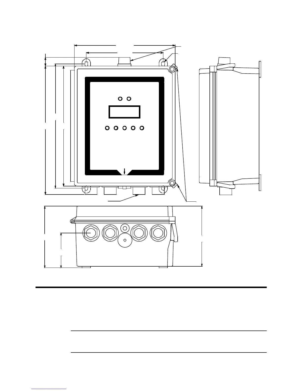
Figure 4: Beacon 410 Gas Monitor Outline and Mounting Dimensions
Wiring the Beacon 410 Gas Monitor
This section describes procedures to connect the AC power source, DC power source,
Modbus wiring (refer to “Wiring the Beacon 410 in a Modbus System” on page 55),
external alarms, recording devices, and detector heads. See Figure 5 on page 17 for a
general diagram of all external wiring to the Beacon 410.
WARNING: Make all connections to the Beacon 410 before you plug in or turn on
the AC or DC power source. Before you make any wiring adjustments,
always verify that all power sources are not live.
Door Latches
Ø .31 x .50 slot, 4X
Strobe (Optional)
3/4" Conduit Hubs, 4X
12.50
12.94
13.39
3.63
6.43
10.50
6.25
8.00
.90