Beacon 410 Gas Monitor Operator’s Manual Internal Description • 9
Buzzer
The buzzer is on the bottom of the housing, behind the reset switch. The buzzer sounds
an audible alarm to warn you of gas alarms and instrument failures.
Internal Description
This section describes the internal components of the Beacon 410.
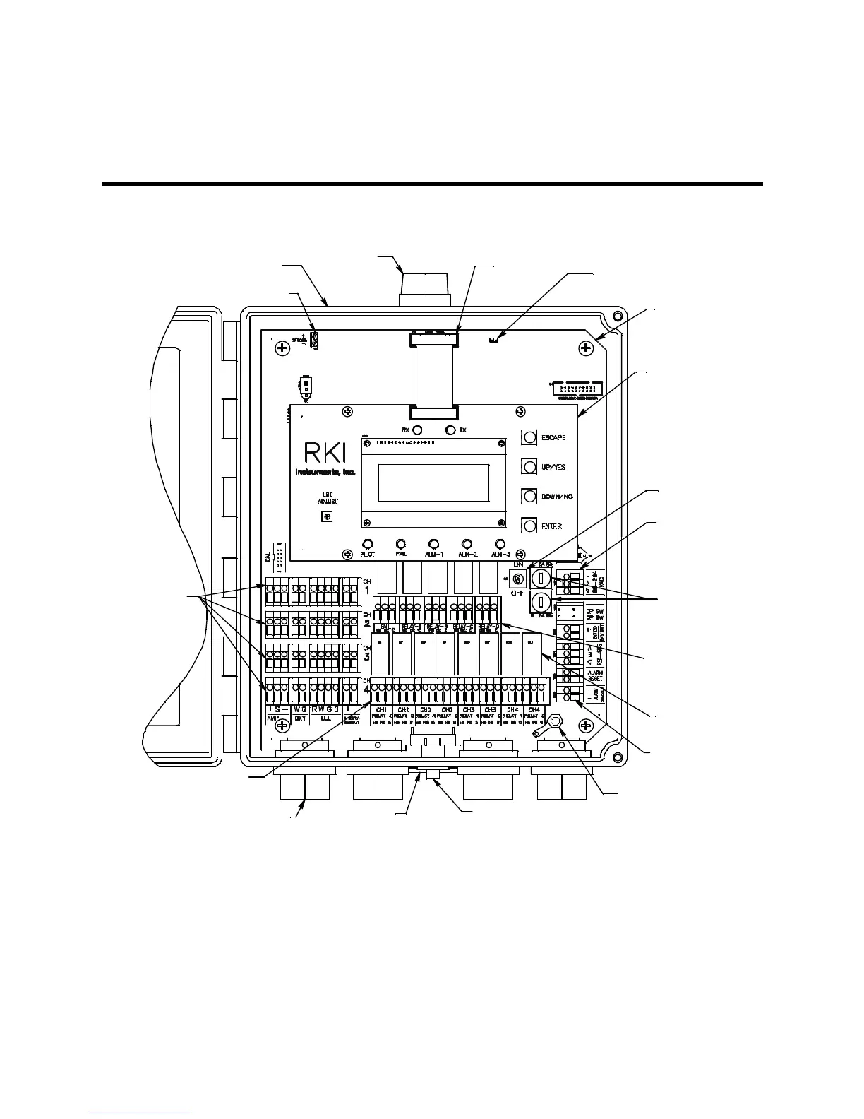
Figure 1: Beacon 410 Gas Monitor Component Location
Control PCB
The control PCB (printed circuit board) is mounted to the power supply mounting plate
which is in turn mounted to the main PCB. The power supply mounting plate and main
PCB are described below. The control PCB includes the LCD display, the LCD contrast
adjust pot, the status LEDs, and the program buttons.It is connected to the main PCB by
the display cable which is a 20 conductor ribbon cable assembly. The display cable
connects to a rectangular connector on the top edge of the control PCB and to the same
type of connector labelled “FRONT PANEL” on the top edge of the main PCB.
Main PCB
Control PCB
Relay (13X)
Ground Stud
Controller
Terminal Strip
AC Fuse (2X)
Display
Cable
Power Switch
Reset Switch
Optional
Strobe
Buzzer
Detector/
Transmitter
Terminal
Strips
Common/
Channel Alarm
Terminal Strip
Channel Alarm
Terminal Strip
Termination
Jumper
3/4 " Conduit Hub (4X)
Housing
Strobe Terminal Strip
AC In
Terminal Strip
 Loading...