Beacon 410 Gas Monitor Operator’s Manual Starting Up the Beacon 410 Gas Monitor • 23
CAUTION: The power switch does not control DC input power.
3. See the transmitter’s operator’s manual for instructions on how to connect wires to the
transmitter.
4. Install an appropriately rated cable bushing or conduit in an unused conduit hub on
the bottom of the Beacon 410 housing.
5. Route the wires from the transmitter through the selected conduit hub into the Beacon
410.
6. Connect the wires from the transmitter to the appropriate channel’s
detector/transmitter terminal strip. See the transmitter operator’s manual for controller
terminal connections and wiring recommendations.
CAUTION: Do not route power and transmitter wiring through the same conduit hub. The
power wiring may disrupt the transmission of the transmitter’s signal to the
Beacon 410.
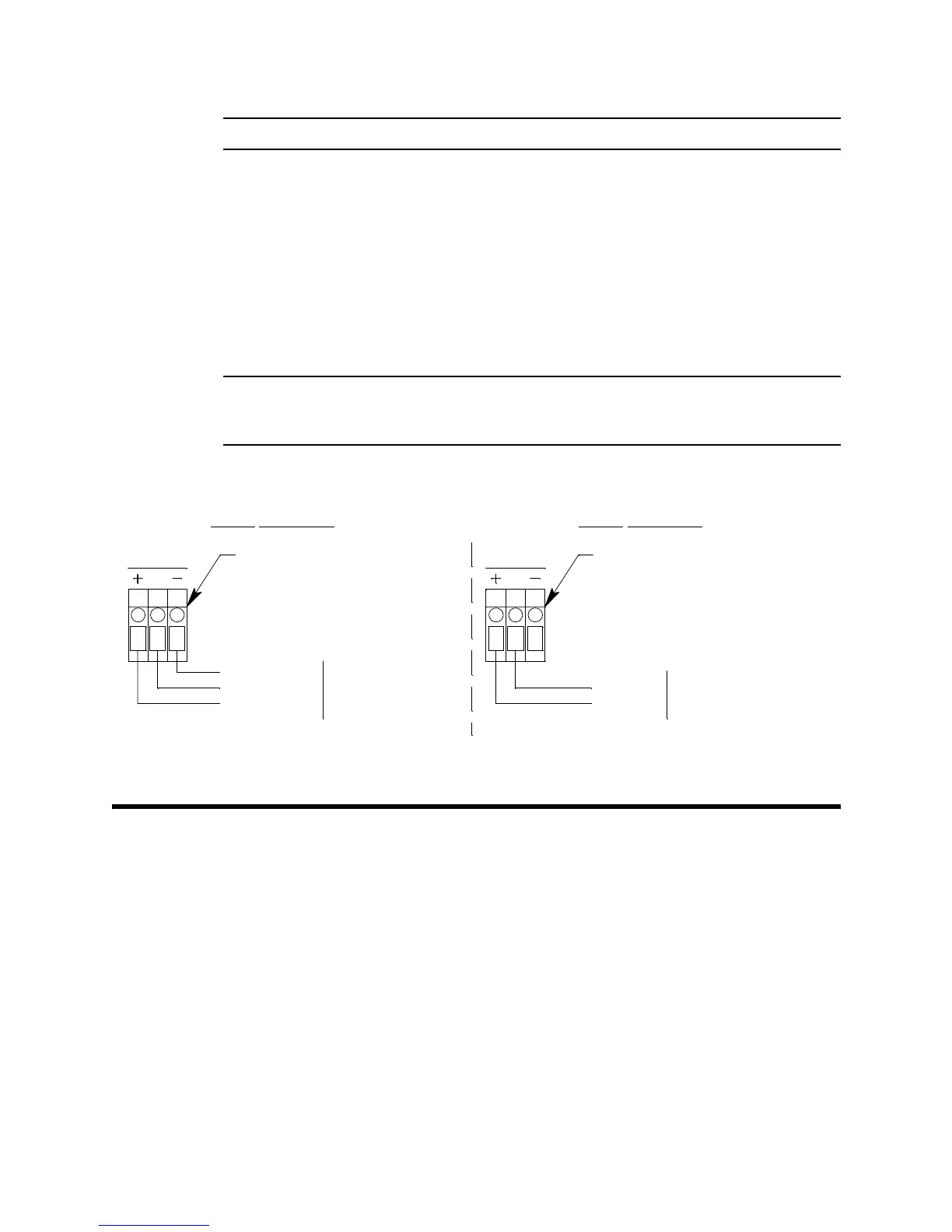
Figure 10 below illustrates typical transmitter wiring connections.
Starting Up the Beacon 410 Gas Monitor
Perform the following procedure to place the Beacon 410 into normal operation.
1. Complete the mounting and wiring procedures described earlier in this chapter.
2. Complete all installation procedures described in the detector head or user supplied
4 - 20 mA transmitter operator’s manuals.
3. Verify that all wiring connections are correct and secure and that the Beacon 410’s
power switch is in the OFF position.
4. Plug in or turn on the incoming power source (AC or DC).
5. Turn on the power switch if AC power is used as primary power.
2-Wire Connection3-Wire Connection
4 - 20 mA Transmitter Terminals
From Detector/Transmitter
Terminal Strip, Typical of 4
4 - 20 mA Transmitter Terminals
From Detector/Transmitter
Terminal Strip, Typical of 4
S
AMP
4 - 20 mA
+ 24 VDC
2-Wire 4 - 20
mA Transmitter
3-Wire 4 - 20
mA Transmitter
- (DC Ground)
4 - 20 mA
+ 24 VDC
S
AMP
Figure 10: Generic 4 to 20 mA Transmitter Wiring