INITIAL INSTALLATION
Figure 3
9
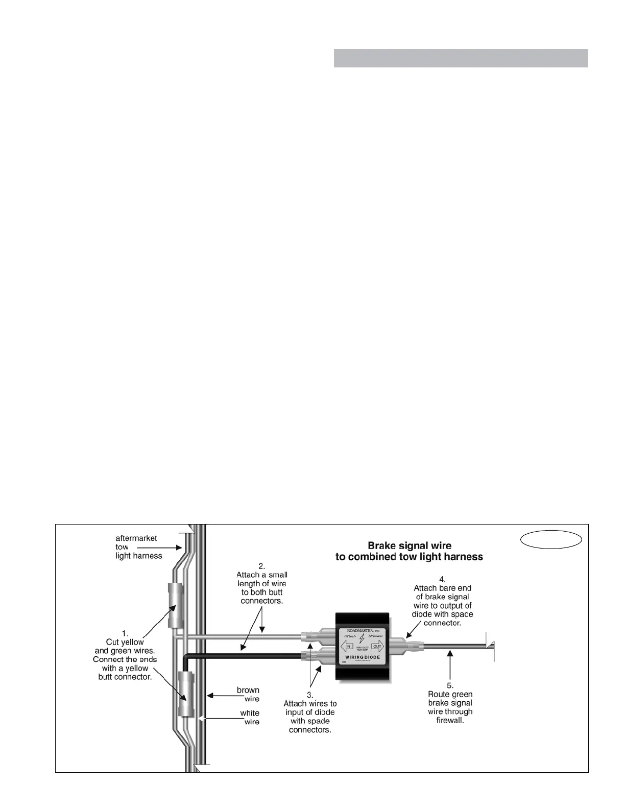
method(2a,above).
3. Usinganotherofthesuppliedspadeconnectors,at-
tachthebareendofthebrakesignalwiretotheoutput
ofthediode(Figure3).
4. Routethebrakesignalwirethroughtheenginecom-
partment, to the driver’s side of the firewall. Use the
same route asthebreak away wiring harness and/or
themotorhome monitorwiringharness, ifthatis con-
venient. As before, avoid lines, hoses, moving parts
or“hot”componentssuchasexhaustsystems.Where
appropriate, use wire ties to secure the brake signal
wireinplace.
5. Routethebrakesignalwirethroughthesamehole
in the firewall as the break away wiring harness and
themotorhomemonitorwiringharness.
6. Replacetheprotectiveloom,whichyouremovedin
stepone.
Step E
Attach the firewall grommet;
attach the wiring connectors
1. Cutthroughtheincludedfirewallgrommet(Figure1)
ononeside,andslideitoverthebreakawaywiringhar-
ness,thebrakesignalwire,andthemotorhomemonitor
wiringharness.Fitthegrommetintothe1/2"holeyou
drilledinthefirewall.Feedtheremaininglengthsofthe
brake signalwire and the breakaway wiringharness
through the grommet. Then,seal the grommet with a
siliconesealant.
2. WhenAddaBRAKEisconnectedanddisconnected,
continued on next page
Attach the brake signal wire
continued from preceding page
2c.Ifthetowedvehiclehasmagnetictowlights…
Note: additional connectors and — depending on the
application — additional wiring will be necessary to wire a
magnetic tow light system.
• Peelbackasectionoftheprotectivecoveringnearthe
plugontheelectricalcable—enoughtouseatestlighton
thewiringand,later,toattachtwobuttconnectors.Then,
usingatestlight,findtheleftandrightcombinedbrake
andturnsignalwires.
• Cutoneofthecombinedbrakeandturnsignalwires,
andattachtheendswithabuttconnector.Runasmall
lengthofwirefromthebuttconnector,andattachafemale
bulletconnectortotheendofthewire.
Attachamalebulletconnectortoanothersmalllength
ofwire.Usingoneoftheincludedspadeconnectors,at-
tachtheotherendofthewiretooneoftheinputsonthe
diode.
Repeatfortheotherbrakeandturnsignalwire.
Beforetowing,connectthemaleandfemalebullet
connectors.
• Trimtheprotectivecoveringovertheelectricalcable;
wrapanyexposedwiringwithelectricaltape.
• Connecttoground—atbothvehicles,connectawire
toanygoodchassisground.Beforetowing,connectthe
groundwireswithaseparatecable.
2d. Ifthetowedvehiclehasataillight(“bulbandsocket”)
wiring kit…
• Makecertainthatagroundconnectionexistsbetween
thetowedvehicleandthemotorhome.Otherwise,thewir-
ingisidenticaltothecombinedbrakeandturnsignallight