Modifications to the towed
vehicle’s lighting system
continued from preceding page
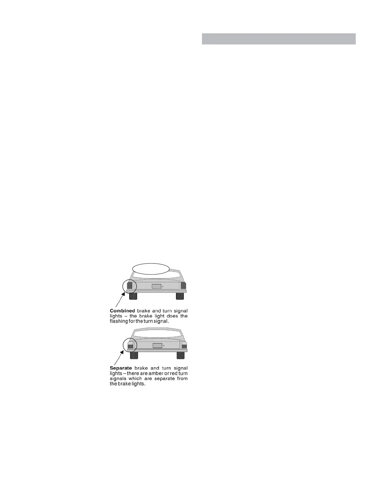
lightdoestheflashingfortheturnsignal;inaseparate
system(Figure 2), thereareamber orred turnsignal
lightswhichareseparatefromthebrakelights.
2. Next,testtoseeifthetowedvehicle’sbrakelights
willilluminatewiththeengineoff—turntheignitionkey
tothe“tow”position,pressthebrakepedal,andcheck
thebrakelights.
3. Basedonwhetherornotthebrakelightsilluminate,
andthetypeofbrakeandturnsignals,therearethree
possibilities:1)thebrakelightsilluminateandthetowed
vehicle has combined lighting;2) the brake lightsil-
luminateandthetowedvehiclehasseparatelighting;
or 3) the brakelights do not illuminate. Choose from
the appropriate listbelow toinstall either an optional
accessoryoranotherlightingsystem.
(If you choose to install a system of diodes and
rewire the vehicle’s turn signals, taillights and brake
lights for towing, wiring diagrams are available at
www.roadmasterinc.com.)
1. If the brake lights illuminate and the
towed vehicle has combined lighting…
…oneofthethreealternativesbelowisrequired.
A. Asystem ofdiodes
(the vehicle’s turn sig-
nals,taillightsandbrake
lightshavebeenrewired
for towing) with an op-
tionalBrake-LiteRelay.
(Thismethodcannot
beusedinFordvehicles
with ‘neutral tow’ kits.
See “Ford ‘neutral tow’
vehicles,”inthismanual,
forwiringinstructions.)
B. Install a “bulb and
socketset”(alsocalleda
“taillightwiringkit,” part
number155).
C. Install a magnetic
towlightsystem(partnumber2100or2120).
2. If the brake lights illuminate and the
towed vehicle has separate lighting…
…oneofthefouralternativesbelowisrequired.
A. Asystemofdiodes(thevehicle’sturnsignals,tail-
lights and brake lights have been rewired for towing)
withanoptionalBrake-LiteRelay.
(ThismethodcannotbeusedinFordvehicleswith
‘neutraltow’kits.See“Ford‘neutraltow’vehicles,”in
thismanual,forwiringinstructions.)
B. Asystemofdiodeswith the diodes jumped.This
methodisalsousedtowireFordvehicleswith‘neutral
tow’kits.SeeFigure15.
C. Installa“bulbandsocketset”(alsocalleda“taillight
wiringkit,”partnumber155).
D. Install a magnetic towlightsystem (part number
2100or2120).
3. If the brake lights do not illuminate…
…an optional stop light switchmust be installed.
ROADMASTERmanufacturesstoplightswitchkitsfor
anumberofvehicles;visitwww.roadmasterinc.comfor
themostcurrentlistofavailablekits.
Anyoneofthefollowingtowlightingsystemsmust
alsobeinstalledwiththestoplightswitch:
• asystemofdiodes(thevehicle’sturnsignals,tail-
lightsandbrakelightshavebeenrewiredfortowing)
• a “bulb and socket set” (also called a “taillight
wiringkit,”partnumber155)
• amagnetictowlightsystem(partnumber2100or
2120)
Step C
Install the motorhome monitor
wiring harness in the towed vehicle
When the components of the motorhome monitor
areinstalledandconnected,anLEDonthemotorhome
dashboardwillilluminateeachtimeAddaBRAKEisac-
tivated,confirmingthatthetowedvehicle’sbrakeshave
beenapplied.
Note: there are two lengths of black wire in this kit,
each with a female bullet connector at one end. Use
the short length of wire in this step.
1. Chooseamountingpointatthefrontofthevehicle,
near the electrical socket, for the end of the harness
withthefemalebulletconnector.Attachtheconnector
withoneormoreoftheincludedwireties.Allowenough
slack sothat a male bulletconnectorcanbe plugged
intoandoutofit.
Note: if there is an open terminal available on both
electrical sockets, you can use the existing electrical
cord to connect the monitor wiring between the two
vehicles. This method eliminates a separate patch cord,
included with AddaBRAKE for the same purpose. If you
choose this method, cut the female bullet connector off,
and attach the monitor wire to the open terminal on the
towed vehicle’s electrical socket. Later, you will use the
matching terminal on the motorhome’s electrical socket
to complete the connection.
continued on next page
INITIAL INSTALLATION
Figure 2
7