Attach the firewall grommet;
attach the wiring connectors
continued from preceding page
the AddaBRAKE wiring harness will be plugged into
and out of the connectors on the break away wiring
harnessandthebrakesignalwire.
Withthisinmind,chooseasuitablelocationforthe
end of the break away harness and the end of the
brakesignalwire—bothconnectorsmustbewithineasy
reach,but must not present an obstacle orhazard to
thedriverofthevehicle,orotherwiseinterferewiththe
operationofthevehicle.
Ifnecessary,coilthebreakawayharnessand/orthe
brake signalwire. Then, attach them at the point you
haveselected,usingoneormoreoftheincludedwire
tiestosecuretheminplace.
Step F
Install the motorhome monitor LED
Note: there are two lengths of black wire in this kit,
each with a female bullet connector at one end. Use
the long length of wire in this step.
Note: some motorhomes are manufactured with aux-
iliary wires pre-strung from the rear of the motorhome
to the dashboard, for aftermarket accessories such as
this. Call the manufacturer.
1. Attachtheendoftheblackwirewiththefemalebul-
letconnector tothe back ofthe motorhome,nearthe
electricalsocket.
Attachthe connector withoneormore of the in-
cluded wire ties. Allow enough slack so that a male
bulletconnectorcanbepluggedintoandoutofit.
Note: in Step C, you may have chosen to use
open terminals on the electrical sockets to connect the
INITIAL INSTALLATION
monitor wiring between the two vehicles. If this is the
case, cut the female bullet connector off, and attach
the monitor wire to the open terminal on the motorhome
electrical socket.
2. Oncethefemalebulletconnectorisattached,route
thewirefromthebackofthemotorhometotheunder-
sideofthedashboard.Avoidlines,hoses,movingparts
(slideouts, sliding generators, sliding battery trays) or
“hot” components such as exhaust systems. Where
appropriate, use wire ties to secure the wire to the
undercarriage.
3. ChooseanareaonthedashboardtomounttheLED.
Lookforamountingpointawayfrompre-existingwires
orcomponents,wheretheLEDcanbeeasilyseenby
thedriver.
4. Drilla5/16"holethroughthedashboardatthepoint
youhavechosen.Beforedrilling,makecertainyouwill
notdamageanycomponentsontheotherside.
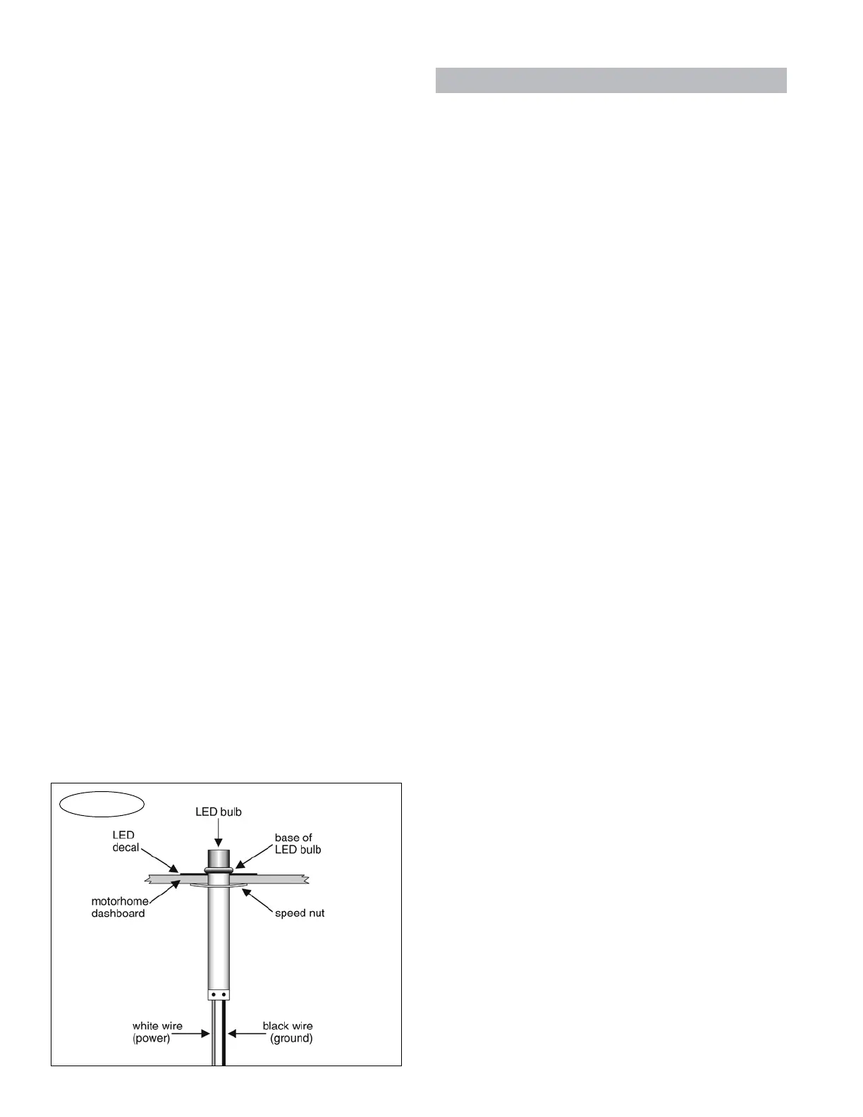
5. CentertheLEDdecal(Figure4)overthehole,and
press itdown. Or,you maychoosetoomit thedecal,
dependingonyourpreferences.
6. Fromthetopofthedashboard,slidetheLEDthrough
thehole,wiresfirst,untilthebaseof thebulb(Figure
4)isflushtothetopofthedash.
7. Fromtheundersideofthedash,fitbothofthewires
throughthespeednut(Figure4).Thenpushthespeed
nutup,againstthedash,tosecuretheLEDinplace.
8. Usingoneormoreofthesuppliedwireties,attach
theaudiosignalcircuitboard(see“Components,”page
two)totheundersideofthedash,asclosetotheLED
aspossible.
9. Connecttopower—trimtheblackwire,whichyou
routedfromthebackofthemotorhome.(Savetheex-
cess;youmayuseitinthenextstep.)Then, connect
the black wire to both the red LED wire and the red
audiosignalwire,usingtheincludedbuttconnector.
10. Connecttoground—connecttheblackwirefromthe
LED, as well as the black wire from the audio signal
circuit board, to any good chassis ground, using the
included ring terminal. (If necessary, use any excess
wire from the preceding step to extend the length of
thetwogroundwires.)
Step G
Test the braking system
Note: the motorhome and towed vehicle must be
stationary for the system test, and ready for towing —
all components of the braking system must be properly
connected and receiving power. Then, according to the
manufacturer, make all adjustments necessary to pre-
continued on next page
Figure 4
10