I
n addition to wiring and connection instructions, this section contains information about the components of
yoursupplementary brakingsystem, andhowtheyfunction. Forthatreason,read thissection,evenifyouwill
notbeinstallingthesecomponentsyourself.
Step A
Install the break away system
“Breakaway”systemsaresecondarysafetydevices,
required by law in many states, which will brake the
towed vehicleifitseparates (“breaksaway”) fromthe
motorhome.
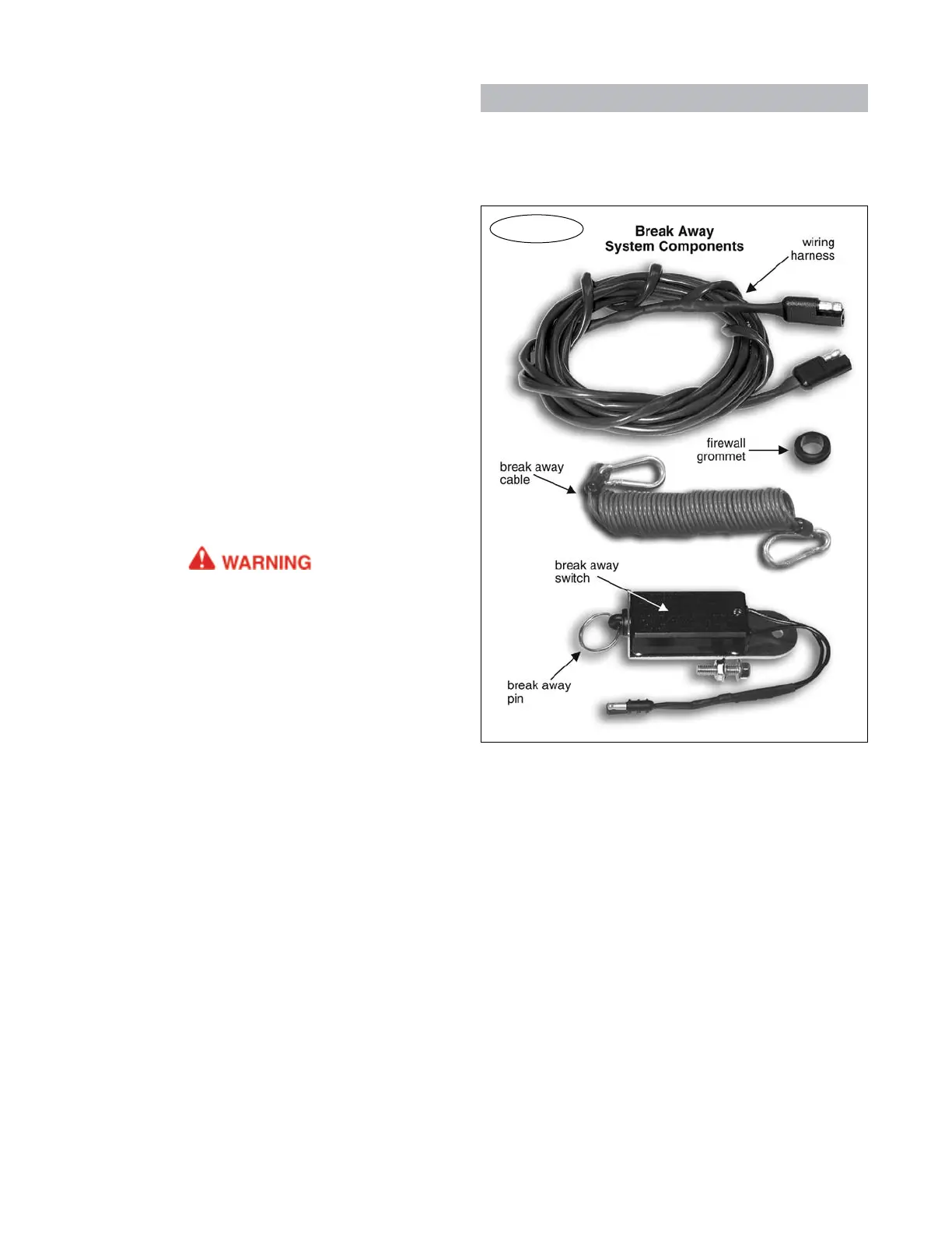
1. Mountthebreakawayswitch(Figure1)atthefront
ofthevehicle,onthedriver’sside.Chooseanareayou
caneasilyreach,withasurfaceofsufficientstrengthto
holdtheswitchfirmlyinplace,sothatthebreakaway
pin(Figure1)willpullfreelyfromtheswitch.Mountthe
switchinahorizontalposition,withthebreakawaypin
facingtowardthemotorhome.
Ensurethatthebreakawaypincanbepulledfree-
ly away from the towed vehicle, without any obstruc-
tions.
Do not attach the break away switch to the tow
bar or the tow bar bracket. If the tow bar or bracket
fails, the break away switch will separate with it,
preventing the break away system from activating.
If the towed vehicle separates, the brakes will not
be applied, which may cause property damage, per-
sonal injury or even death.
2. Thebreakawaywiringharness(Figure1)connects
thebreakawayswitchtoAddaBRAKE.Itwillberouted
throughthefirewall,onthedriver’sside.
Lookforapre-existingholeinthefirewall(or,ifthere
issufficient space, a pre-existinggrommet with other
wiring)closetotheflooronthedriver’sside, toroute
thebreakawaywiringharnessthroughthefirewall.
Note: the motorhome monitor wiring harness (Step
C) and the brake signal wire (Step D) will also be routed
through this hole.
Ifthereisnopre-existingholeorgrommetwithsuf-
ficientspace,drilla1/2"holethroughthefirewall.
Drillfromtheenginecompartmentorfromthein-
terior of the vehicle, whichever is more convenient.
Beforedrilling,makecertainyouwillnotdamageany
componentsontheothersideofthefirewall.
3. Routethewiringharnessfromthebreakawayswitch
tothefirewall(or,fromthefirewallto thebreak away
switch,whicheverismoreconvenient),avoidinglines,
hoses,movingpartsor“hot”componentssuchasex-
haustsystems.
Whereappropriate,usewiretiestosecurethebreak
Figure 1
INITIAL INSTALLATION
awaywiringharness.
Atthefrontofthevehicle,connectthewiringhar-
nesstothebreakawayswitch.
Youwillconnectthebreakawaywiringharnessto
AddaBRAKEinalaterstep.
Step B
Modifications to the
towed vehicle’s lighting system
Asupplementalbrakingsystemwillaffecttheopera-
tion of the vehicle’s tow lighting system. Use the fol-
lowinginformationtodetermineifoptionalaccessories
mustbeinstalledinavehiclewhichhasbeenwiredfor
towing — or, if no lighting system has been installed,
whichsystemsareappropriate.
1. First, identify the type of brake and turn signals
in the vehicle. There are two types — combined or
separate.Inacombinedsystem(Figure2),thebrake
continued on next page
6