4
ATTACHING THE TRACKER — REMOVABLE BASEPLATE
There are two ways to attach the Tracker to the towed
vehicle. They depend on the type of baseplate:
1) If the towed vehicle has a classic baseplate, the
crossbar is bolted to the baseplate. With this method, the
crossbar remains attached to the front of the towed ve-
hicle.
Use the instructions on the preceding page to attach
the Tracker to a classic baseplate.
2) If the towed vehicle has a removable baseplate
(ROADMASTER XL
™
or EZ Twistlock
™
series), the cross-
bar, as well as the front extensions of the baseplate, can
be easily removed from the front of the vehicle when it is
not being towed.
An optional set of “quick-disconnects” (or, “QDs”, part
number 201) is required for this method.
Use the instructions below to attach the Tracker to a
removable baseplate.
Attaching the Tracker
— removable baseplate
(An optional set of “quick-disconnects” — or, “QDs”, part
number 201 — is required for this method.)
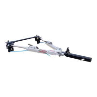
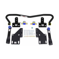
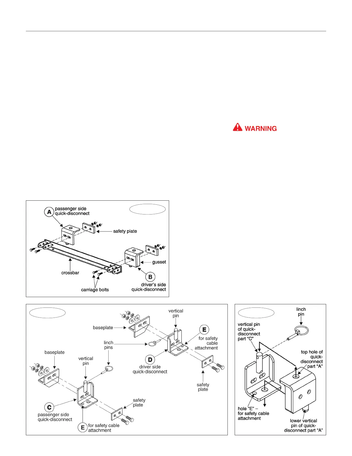
First, attach quick-disconnect parts “A” and “B” (Figure
Figure 7
Figure 6
6) to the Tracker safety base:
1. Align the holes in parts “A” and “B” over the holes at
each side of the Tracker crossbar. Make certain that part
“A” is on the passenger side, and part “B” is on the driver’s
side — the gussets (Figure 6) will be on the outside.
Thread one of the supplied carriage bolts (Figure 6)
through each hole, and through the quick-disconnects.
2. At each end, position one of the safety plates (Figure
6) over the carriage bolts.
3. Thread a lock washer and nut over each carriage bolt
to secure the safety plates and the quick-disconnects to
the Tracker crossbar. Finger-tighten only at this time.
Use all mounting hardware and the safety plates. If
all supplied materials are not used, the quick-discon-
nects or other components may vibrate loose, which
may cause property damage, personal injury or even
death.
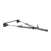
4. Next, attach quick-disconnect parts “C” and “D” (Figure
7) to the baseplate. Attach parts “C” and “D” so that the
vertical pin on each is pointing up, as shown in Figure 7.
Attach part “C” on the passenger side, and part “D”
on the driver’s side. Use the supplied ½" x 1¾" bolts, the
two safety plates, and the flat washers, lock washers and
nuts, as shown in Figure 7.
Note that both QDs have an extra hole — “E” in Figure
7 — for safety cable attachment. Mount parts “C” and “D”
so that the “E” holes are to the outside.
Do not tighten any of the bolts — leave them loose for
now — they will be tightened later.
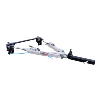
5. Now, test-fit the crossbar — lower the crossbar over the
quick-disconnects. The vertical pins at the top of both QDs
should fit through the top holes at the ends of the crossbar
(Figure 8), and the vertical pins at the bottom of the cross-
continued on next page
Figure 8