5
cal pins on both quick-disconnects. Refer to Figure
9.
Failure to properly attach and lock both linch pins
will result in the loss of the towed vehicle, which
may cause property damage, personal injury or even
death.
(ROADMASTER recommends replacing at least one
linch pin with a padlock — part number 301 or 302 — to
prevent accidental release or theft.)
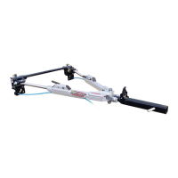
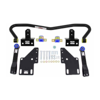
Attaching the Tracker —
removable baseplate
continued from preceding page
bar should fit through the lower holes on the quick-dis-
connects (Figure 8).
6. The quick-disconnects must be positioned so that the
tow bar is centered on the front of the vehicle.
If necessary, adjust the quick-disconnects by moving
them to the left or the right, until the tow bar is centered
to the front of the vehicle.
CAUTION
The quick-disconnect parts “C” and “D” must be
centered on the baseplate. If parts “C” and “D” are
mounted too far to the left or the right, the tow bar
will not be centered on the towed vehicle, which will
cause excessive tire wear and other consequential,
non-warranty damage.
7. Once the crossbar slides on and off easily, torque the
four bolts to 75 ft./lbs.
Again, test-fit the crossbar over the QDs, to verify that
the crossbar slides on and off easily. If not, adjust the QDs
again.
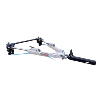
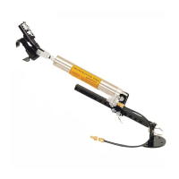
8. Insert the two linch pins (Figure 9) through the upper
holes in the vertical pins on both QDs. Both linch pins
must be locked. The rings are spring-loaded — they must
be snapped over the pin, with the pin touching the ring, in
order to keep the tow bar secure. If a pin does not touch
the ring, rotate the pin around the ring.
Towing vibrations will force the linch pins out un-
less they are properly locked in place over the verti-
CONNECTING THE TRACKER TO THE MOTORHOME
Use caution when handling the tow bar — if your
hands, fingers or any part of your body are caught
between moving components, they can be pinched,
cut or otherwise injured.
1. First, attach the Tracker to the towed vehicle — refer
to either “Attaching the Tracker — classic baseplate,” or
“Attaching the Tracker — removable baseplate.”
2. Drive the vehicle to be towed up to the rear of the mo-
torhome. Put the vehicle in gear (park), set the emergency
brake and chock one of the wheels.
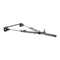
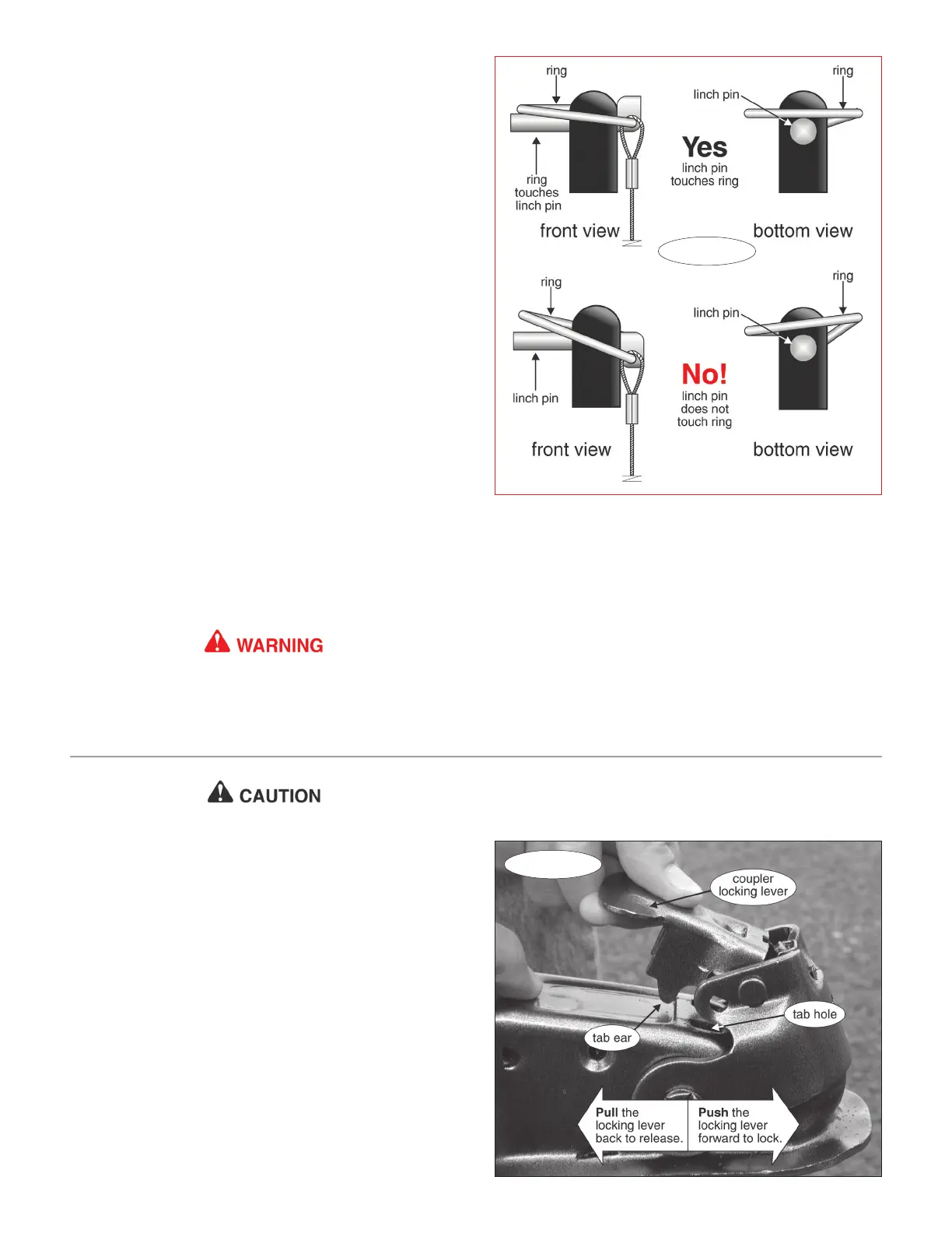
3. Lower the tow bar to position the coupler (Figure 10)
over the hitch ball.
With the coupler over the ball, raise the coupler locking
lever (Figure 10) until the tab ‘ear’ (Figure 10) just clears
the tab hole (Figure 10), and pull straight back toward the
towed vehicle.
Next, lower the coupler over the hitch ball so that it
completely covers it, and push the coupler locking lever
forward until it locks on the ball.
Figure 10
Figure 9
Note: use an optional coupler lock (part number 305)
for added protection against accidental coupler disconnect.
continued on next page