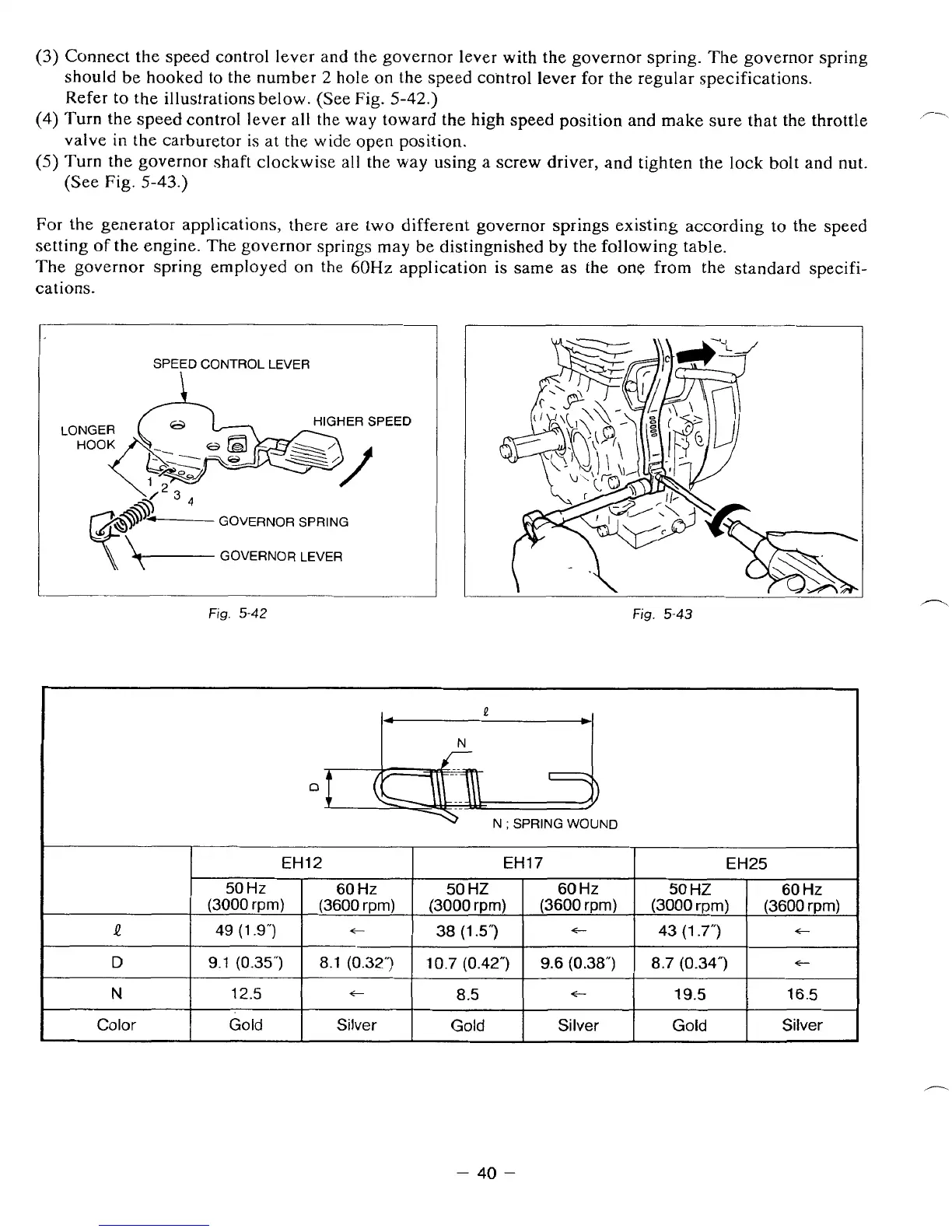
(3)
Connect the speed control lever and the governor lever with the governor spring. The governor spring
should be hooked to the number
2
hole
on
the speed control lever for the regular specifications.
Refer to the illustrations below. (See Fig.
5-42.)
valve
in
the carburetor
is
at the wide
open
position.
(See Fig.
5-43.)
(4)
Turn
the speed control lever all the way toward the high speed position and make sure that the throttle
(5)
Turn
the
governor shaft clockwise all the way
using
a screw driver, and tighten
the
lock bolt and nut.
P\
For
the generator applications, there are
two
different governor
springs
existing according
to
the speed
setting of
the
engine. The governor springs may be distingnished by the following table.
The governor
spring
employed
on
the
6OHz
application
is
same
as
the
one
from the standard specifi-
cations.
SPEED CONTROL LEVER
GOVERNOR SPRING
\\
f-
GOVERNOR LEVER
Fig.
5-42
Fig.
5-43
Et
50
Hz
(3000
rpm)
Q
12.5
N
9.1 (0.35")
D
49 (1.9")
Color
Gold
N
;
SPRING WOUND
12
EH25
EH17
60
Hz
(3600
rprn)
(3000
rprn)
(3600
rpm)
(3000
rpm)
(3600
rpm)
60
Hz
50
HZ
60
Hz
50
HZ
t
t
43
(1.7")
t
38
(1
5")
8.1
(0.32")
c
8.7 (0.34")
9.6
(0.38")
10.7 (0.42")
t
Silver
Gold
Silver
Gold
Silver
16.5 19.5
t
8.5
P
-
40
-