10)
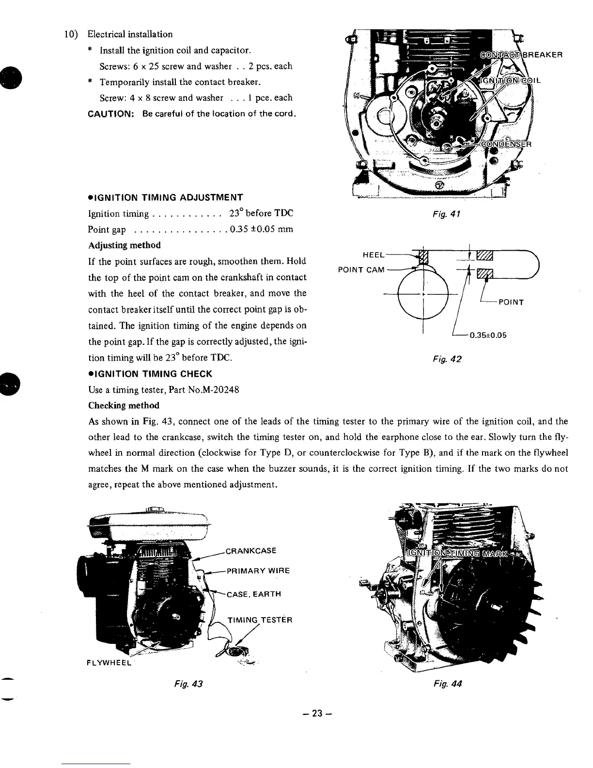
Electrical installation
*
Install the ignition coil
and
capacitor.
Screws:
6
x
25
screw and washer
. .
2
pcs. each
*
Temporarily install the contact breaker.
Screw:
4
x
8
screw and washer
...
1
pce. each
CAUTION:
Be
careful
of
the
location
of
the
cord.
*IGNITION TIMING ADJUSTMENT
Ignition timing
............
23"
before TDC
Point gap
...............
.0.35
k0.05
mm
rKER
Fig.
4
1
Adjusting method
If
the point surfaces are rough, smoothen them. Hold
the top of the point cam on the crankshaft in contact
with the heel
of
the contact breaker, and move the
contact breaker itself until the correct point gap is
ob-
tained. The ignition timing of the engine depends on
the point gap.
If
the gap is correctly adjusted, the igni-
tion timing
will
be
23"
before
TDC.
.IGNITION TIMING
CHECK
Use a timing tester, Part
N0.M-20248
Fig.
42
Checking method
As
shown in Fig.
43,
connect one of the leads
of
the timing tester to the primary wire of the ignition coil, and the
other lead to the crankcase, switch the timing tester on, and hold the earphone close to the ear. Slowly turn the fly-
wheel
in
normal direction (clockwise for Type
D,
or counterclockwise for Type
B),
and if the mark on the flywheel
matches the
M
mark on the case when the buzzer sounds, it
is
the correct ignition timing. If the two marks do not
agree, repeat the above mentioned adjustment.
---"
FLYWHEEL
Fig.
43
Fig.
44
-
23
-