4 HDC2450 Motor Controller Datasheet Version 1.2. July 20, 2010
Important Warning
Carefully follow the wiring Instructions provided in the Read Me First sheet that comes with the control-
ler, or in the Power Connection section of the User Manual. The information on this datasheet is only a
summary.
Mandatory Connections
It is imperative that the controller is connected as shown in the above diagram in order to ensure a safe and trou-
ble-free operation. All connections shown as thick black lines line are mandatory. The controller must be powered
On/Off using switch SW1on the Yellow wire. Use a suitable high-current fuse F1 as a safety measure to prevent
damage to the wiring in case of major controller malfunction.
The battery must be connected in permanence to the controller’s Red wires via a high-power emergency switch
SW2 as additional safety measure.
Precautions and Optional Connections
Note1: Backup battery to ensure motor operation with weak or discharged batteries, connect a second battery to
the Power Control wire/terminal via the SW1 switch.
Note2: Use precharge 1K, 0.5W Resistor to prevent switch arcing.
Note3: Insert a high-current diode to ensure a return path to the battery during regeneration in case the fuse is
blown.
Note4: Optionally ground the VBat wires when the controller is Off if there is any concern that the motors could
be made to spin and generate voltage in excess of 50V.
Note5: Connect the controller’s earth tab to a wire connected to the Earth while the charger is plugged in the AC
main, or if the controller is powered by an AC power supply.
Note6: Beware not to create a path from the ground pins on the I/O connector and the battery’s minus terminal.
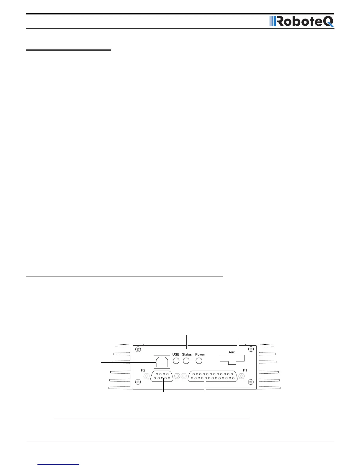
Sensor and Commands Connection
Connection to RC Radio, Microcomputer, Joystick and other low current sensors and actuators is done via the 25
and 9 pin connectors located in front of the connector. The functions of many pins vary depending on controller
model and user configuration. Pin assignment is found in the table below.