Transport and positioning
10
2
Table3.1 Network gas pressure
Gas supply pressure [mbar]
Product category Countries of destination G20 G30 G31 G30 G31
II
2H3B/P
CH, CZ, DK, EE, FI, GR, IT, LT, NO, RO, SE, SI, SK 20 30
AT 20 50
II
2H3P
CH, CZ, ES, GR, HR, IE, IT, LT, PT, SI, SK 20 37
II
2H3+
CH, CY, CZ, ES, GB, GR, IE, IT, LT, PT, SI, SK, TR 20 28-30 37
The appliance gas supply pressure, both static and dynamic, must comply with the values in the Table, with a tolerance of ± 15%.
3.3.5 Vertical pipes and condensate
▶
Vertical gas pipes must be tted with siphon and dis-
charge of the condensate that may form inside the
pipe.
▶
If needed, insulate the piping.
3.3.6 LPG pressure reducers
With LPG the following must be installed:
▶
A rst stage pressure reducer, close to the liquid gas
tank.
▶
A second stage pressure reducer, close to the appli-
ance.
Pressure reducers must always be installed outside
the building.
3.4 COMBUSTION PRODUCTS EXHAUST
Compliance with standards
The appliance is approved for connection to a
combustion products exhaust duct for the types
shown in Table 1.1
p.8
.
3.4.1 Flue gas exhaust and combustion air
intake connection
▶
Ø 60/100 mm on the rear (Figure 1.1
p.8
)
3.4.2 Installation types
The ue gas exhaust/air intake of the TS 2000 gas-red
convectors must be carried out, using the supplied coax-
ial pipes, on the installation wall (maximum pipe length
50 cm).
Warnings
The installation of coaxial pipes with a vertical
downward outlet is prohibited (leads to recircula-
tion of ue gas with lock-out of the appliance).
It is forbidden to install coaxial pipes with a vertical
outlet upwards (due to rain, water, objects inltra-
tion, with consequent lock-out of the appliance).
3.5 INSTALLATION PROCEDURE
In accordance with the installation project, prepare the
gas supply line and make the holes for the ue and com-
bustion air intake pipes.
3.5.1 Install the gas-red convector on the wall
1. Check the packaging for visible signs of damage, oth-
erwise, notify the carrier immediately.
2. Remove the gas-red convector from its packaging
by rst removing the air intake and ue gas exhaust
pipes. Do not damage or discard the cardboard jig
with the drilling template required for installing the
gas-red convector.
3. Fix the jig to the wall where the gas-red convector is
to be installed, making sure it is perpendicular to the
oor.
4. Mark on the wall the holes for the air intake and ue
gas exhaust duct and for the two wall plugs that will
hold the support bracket.
5. Drill the hole (Ø 100 mm) to house the coaxial pipe
and holes to x the support bracket (drill 6 mm holes
to insert the provided wall plugs). The Ø 100 mm hole
for the duct can be made with a suitable core drill or
by means of a succession of smaller holes made with a
simple drill on the perimeter to be removed.
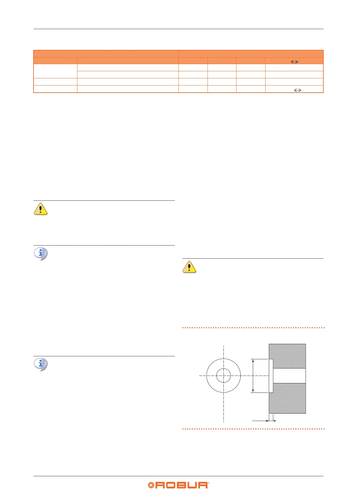
If the appliance is to be installed on a wall cov-
ered with ammable material, such as wallpaper,
matchboarding, etc., part of this must be removed
to a Ø 130 mm around the ue outlet hole to reach
the bare wall. If it is not possible to remove only
the ammable layer (e.g. all-wood walls) it will be
necessary to drill a hole 30 mm deep around the
pipe (see Figure 3.1
p.10
).
Figure3.1 Ø 130 hole drilling
130 mm
30 mm
6. Use the supplied plugs to x the support bracket to
the wall, making sure that the holes at the ends of the
bracket are at the bottom (see Figure 3.2
p. 11
). It
is recommended, even at this stage, to check that the
bracket is parallel to the oor.