Transport and positioning
Installation, use and maintenance manual – TS 2000
11
2
7. Adjust the length of the pipes (intake and exhaust)
to the eective wall thickness, cutting the tract in ex-
cess: for the exact length determination, see Figure
3.3
p.11
.
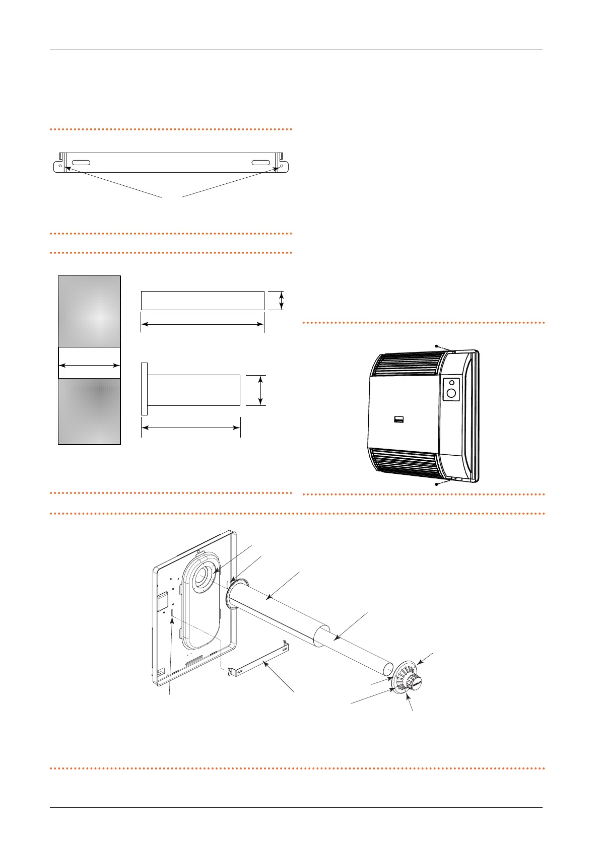
Figure3.2 Correct positioning of the support bracket
A Holes for securing the support bracket to the wall
Figure3.3 Length of intake and exhaust pipes
A Wall thickness
B Flue gas exhaust pipe
C Air pipe
A + 9 cm
A + 1 cm
A
60
100
B
C
8. Remove the casing from the heating body by un-
screwing the screws at the top and bottom (see gure
3.4
p.11
).
9. Insert the ue gas exhaust pipe B in the combustion
chamber. Fit the air pipe C and then x it to the appli-
ance with the screws provided, inserting the sealing
gasket D (see Figure 3.5
p.11
).
10. Place the gas-red convector on the wall by introduc-
ing the intake/exhaust pipe into the hole previously
made and hooking the gas-red convector to the sup-
port bracket by means of the specic holes G on the
back of the gas-red convector (see Figure 3.5
p.11
).
11. Secure the heating body to the wall by tightening the
two locking screws on the support bracket. Further
minor adjustments to the position can be made at this
stage.
12. Connect the gas network as described in Paragraph
3.3
p.9
.
13. Fit the casing and tighten the locking screws (see
Figure 3.4
p.11
).
Figure3.4 Remove the casing by unscrewing the screws
Figure3.5 Installation of coaxial pipes and terminal
A Support bracket
B Flue gas exhaust pipe
C Air pipe
D Gasket
E External windproof terminal
F Holes for xing the terminal
G Support bracket xing holes
A
B
C
D
E
F
G
G