RK3288 Hardware Design Guide
13 DVP Interface & Camera
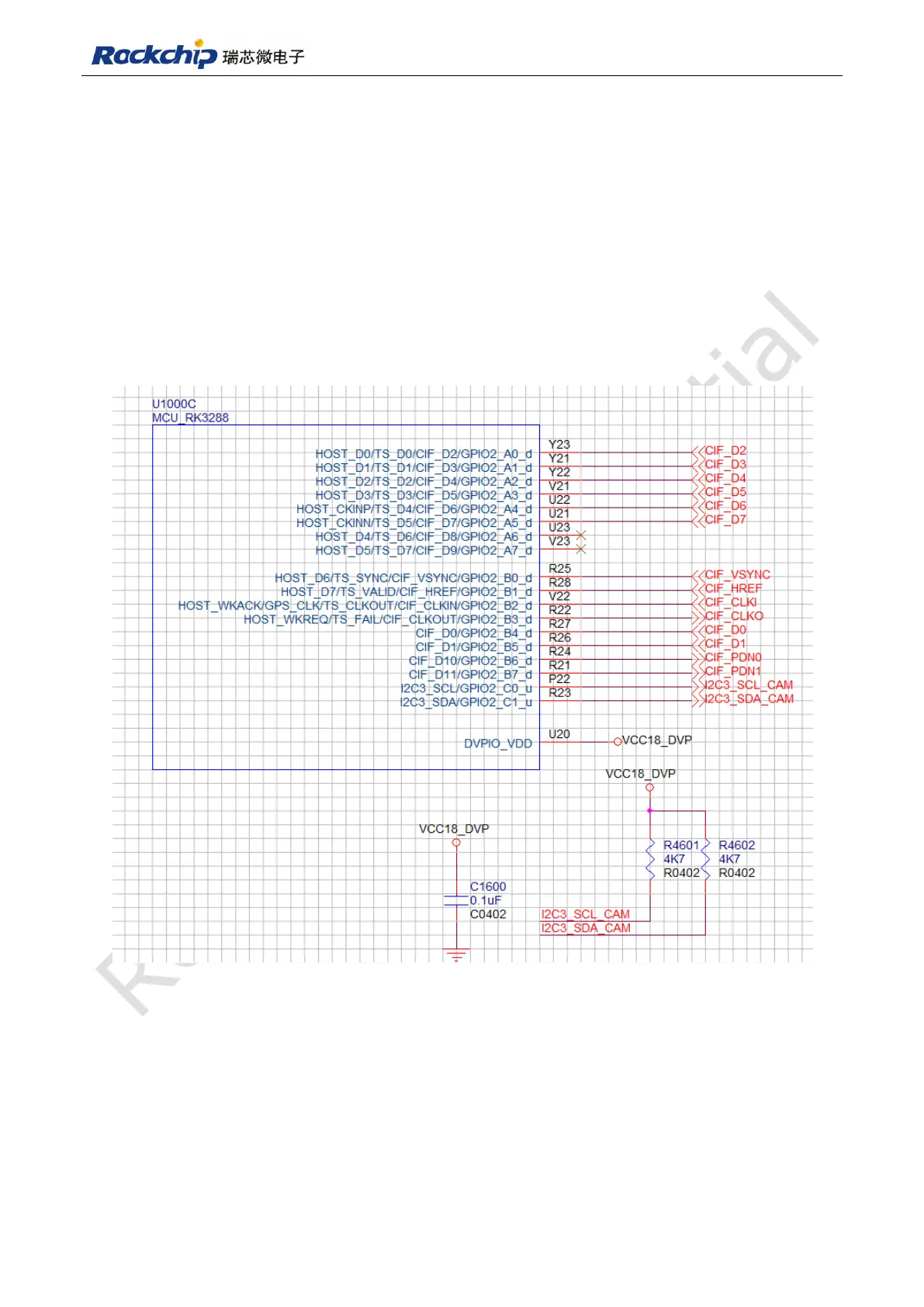
13.1 Schematic
DVP interface power domain supply DVPIO_VDD, in actual product design, IO power
supply requirement (1.8V or 2.8V)should be based on Camera, chose a corresponding power
supply and keep it in the same level with I2C pull-up level, otherwise it will cause Camera
abnormal or disabled working status as shown in Fig 13-1.
Fig 13-1
In order to avoid camera trace length is too long, which will cause timing problem,
abnormal data collection, RC delay circuit as shown in Fig 13-2 should be added. Remember
to pay attention to flow direction of clock signal, and relevant component should be placed
close to signal output terminal.