4
Wiring
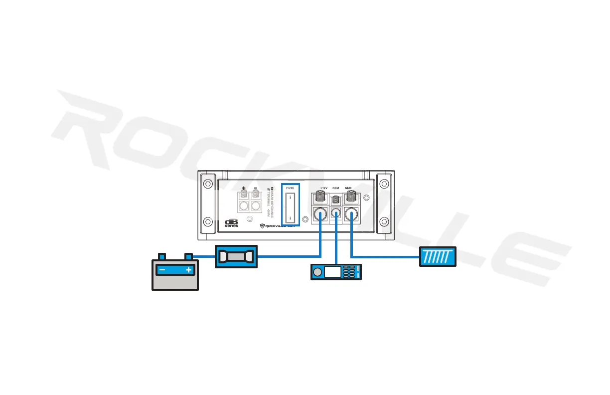
1. Make sure to disconnect the NEGATIVE (-) terminal from your car’s battery.
2. Attach an 8-gauge or heavier wire to the amplier screw terminal marked GND. The connection should be as close to the amp as possible (20 feet or less). For runs of 20 feet or more,
you will need a 4-gauge or heavier wire. When connecting the ground wire, make sure that there is no paint or other insulator blocking a good ground connection. When installing multiple
ampliers, mount them in close proximity so that they can all share the same ground point.
3. Connect the remote terminal to the head unit’s remote output using an 18-gauge or heavier wire. This connection is responsible for turning the amplier on and off with the rest of the
system. If there is no dedicated remote output, make this connection to the power antenna lead. Should your head unit not have any turn-on leads, you can wire the remote terminal to an
accessory lead, which turns the amplier on with your car’s ignition. Please note: Do not connect the remote wire when using the high-level inputs.
4. Use an 8-gauge or heavier wire to connect the screw terminal marked +12V to the battery’s POSITIVE (+) terminal. In order to protect the battery and electrical systems of your car, add
an in-line fuse holder within 18˝ of the battery. This in-line fuse offers protection against damage from short circuits. The power wire should terminate in a large ring terminal connected
directly to the POSITIVE (+) terminal. An optional second fuse can be installed closer to the amplier for additional protection to the amplier itself. If installing multiple ampliers, install
a distribution block near their location and, using a 4-gauge wire, connect the block to the in-line holder that is connected to the battery.
5. Insert fuse(s) into the in-line fuse holder(s) and check that all connections are properly secured.
6. Before powering up the system, set all the amplier’s level controls to minimum, the crossover/setting switches to the desired postion, and the head unit’s volume to 75%.
We have received ampliers back to our service department with melted power/ground terminals caused by a bad ground connection. When there is a lack of good ground, heat builds up
at the contact screws of the amplier terminal. Over time the heat generated will begin to melt the terminal. It is a good practice to feel the power and ground wires near the amplier after
using the amp for a while. If the wires feel hot to the touch, you probably have a bad or loose connection. If after adjusting your connections the wires still feel hot, you should upgrade to
the next heaviest gauge wire. As connections can work loose due to vehicle vibrations, we recommend periodically tightening all power and ground connections.
Never replace the supplied fuse with one of a larger value (see diagram above). Fuse rating available on page 16.
BATTERY
FUSE
GROUND
HEAD UNIT
or THE VEHICLE’S ACCESORY LEAD;
DO NOT CONNECT WHEN USING HIGH-LEVEL INPUTS.
SUPPLIED
FUSE
 Loading...