54 Rockwell Automation Publication 1766-UM001O-EN-P - September 2021
Chapter 3 Wire Your Controller
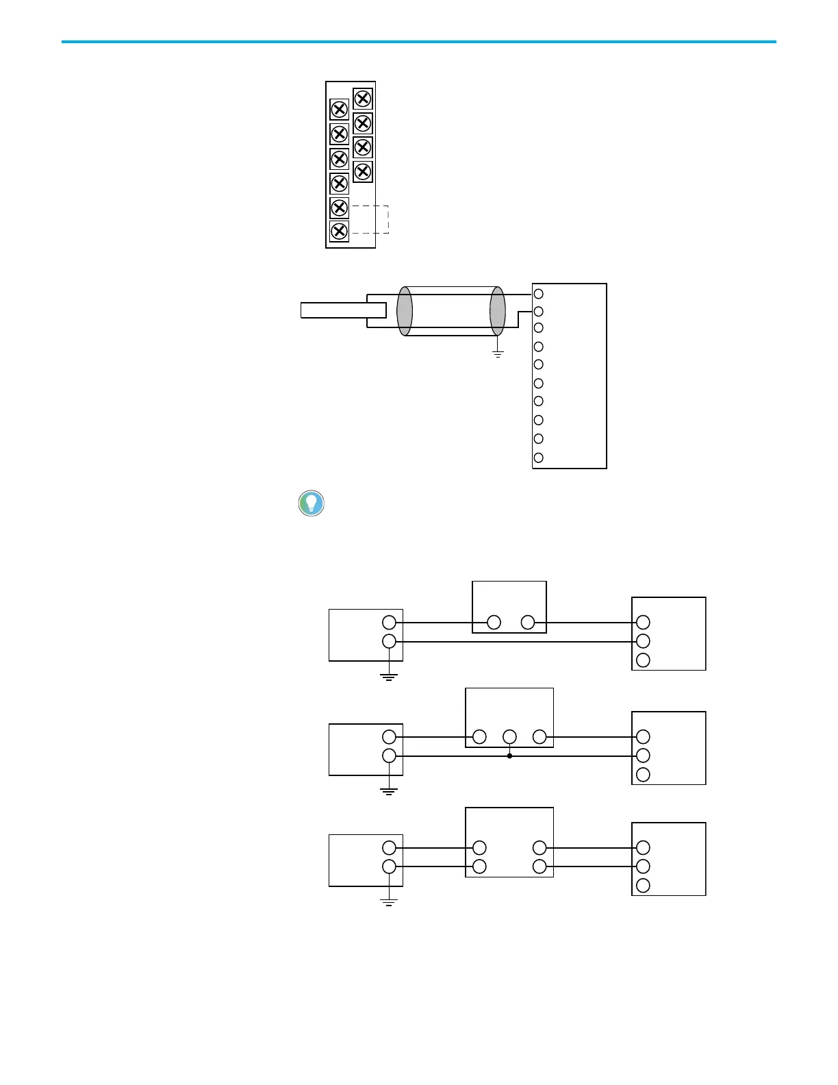
Figure 40 - 1762-IF4 Terminal Block Layout
Figure 41 - Differential Sensor Transmitter Types
Figure 42 - Sensor/Transmitter Types
Grounding the cable shield at the module end only usually provides sufficient noise
immunity. However, for best cable shield performance, earth ground the shield at both
ends, using a 0.01 µF capacitor at one end to block AC power ground currents, if
necessary.
IN 1 (+)
IN 0 (+)
IN 1 (-)
IN 0 (-)
IN 3 (+)
IN 2 (+)
IN 3 (-)
IN 2 (-)
COM
COM
Commons internally connected.
IN 0 (+)
IN 0 (-)
IN 3 (+)
IN 3 (-)
IN 2 (+)
IN 2 (-)
COM
IN 1 (-)
IN 1 (+)
COM
+
+
-
-
+
-
+
-
IN +
IN -
COM
+
-
IN +
IN -
COM
+
-
IN +
IN -
COM
Power
Supply
(1)
Power
Supply
(1)
Power
Supply
(1)
Transmitter
Transmitter
Transmitter
Module
Supply
Signal
2-Wire Transmitter
3-Wire Transmitter
4-Wire Transmitter
1)
All power supplies rated N.E.C. Class 2.
Supply
Signal
Module
Module
 Loading...


