Rockwell Automation Publication 1766-UM001O-EN-P - September 2021 69
Chapter 4 Communication Connections
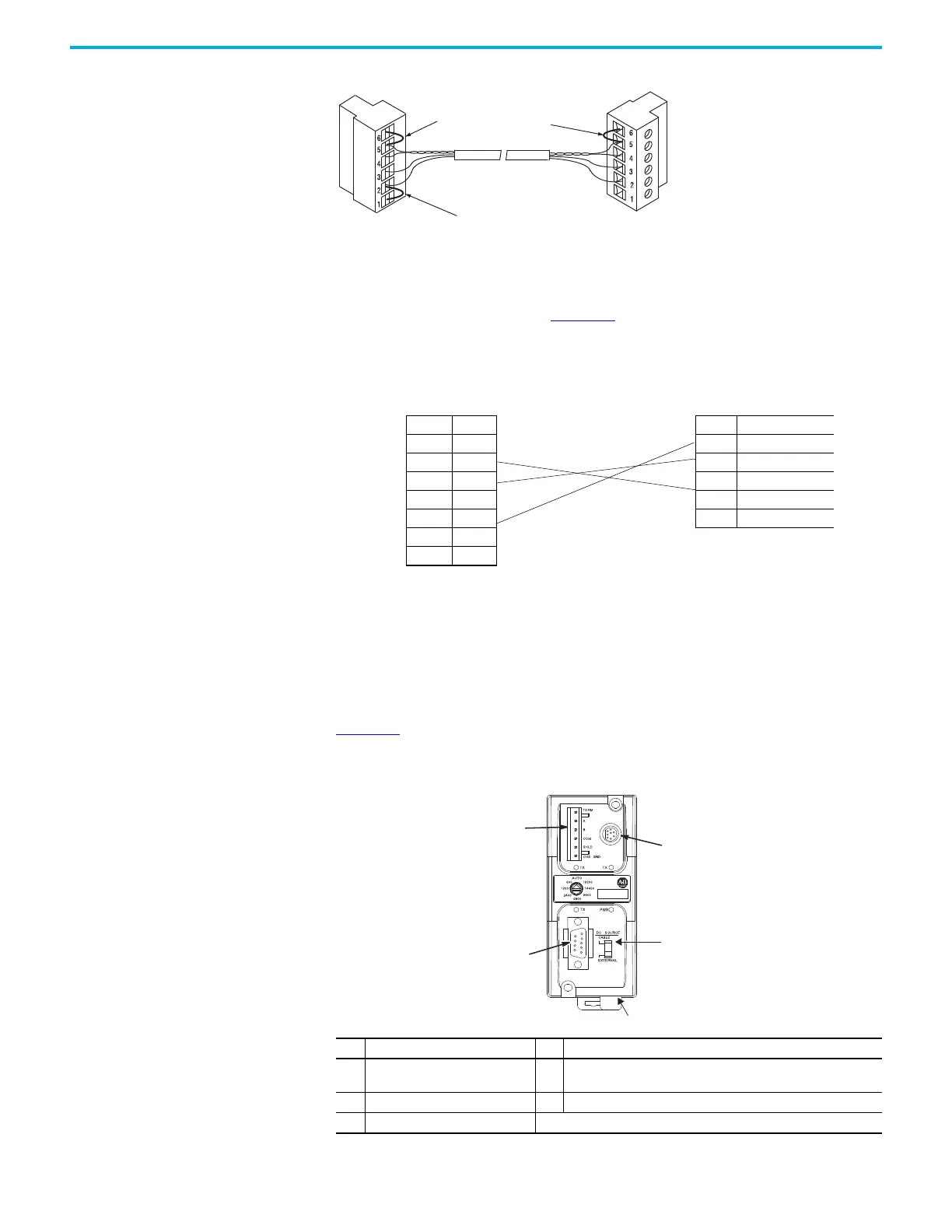
Figure 51 - End-of-Line Termination
MicroLogix 1400 Channel 0 to DH-485 Communication Cable Pinout
When connecting MicroLogix 1400 Channel 0 to DH-485 communication cable
pinout using an RS-232 cable, the maximum that the cable length may be
extended is 15.24 m (50 ft). See Figure 52
.
Figure 52 - DH-485 Communications Cable Pinout
Connect the AIC+ You can connect a MicroLogix 1400 controller to a DH-485 network via
Channel 0 directly without using an optical isolator, such as AIC+, catalog
number 1761-NET-AIC, because Channel 0 is isolated. However, you need to
use an AIC+ to connect your PC or other MicroLogix Family products, such as
MicroLogix 1200, to a DH-485 network.
Figure 53
shows the external wiring connections and specifications of the
AIC+.
Figure 53 - External Wiring Connections
Jumper
Belden #3106A or #9842 cable
1219 m (4000 ft) max
Jumper
Jumper
Jumper
DTE Device
(MicroLogix 1400 Channel 0)
DCE Device (DH-485 connector)
8-Pin 6-pin
7 TXD 6 Termination
4RXD 5A
2GND 4B
1B(+) 3Common
8A(-) 2Shield
5 DCD 1 ChassisGround
6CTS
3RTS
Item Description Item Description
1 Port 1 – DB-9 RS-232, DTE 4
DC Power source selector switch (cable = port 2 power source,
External = external power source connected to item 5)
2 Port 3 – RS-485 Phoenix plug 5 Terminals for external 24V DC power supply and chassis ground
3 Port 2 – mini-DIN 8 RS-232 DTE
AIC+ Advanced Interface Converter
(1761-NET-AIC)
1
2
3
4
5
 Loading...


