Rockwell Automation Publication 1769-IN088A-EN-P - February 2011 107
I/O Memory Mapping Chapter 3
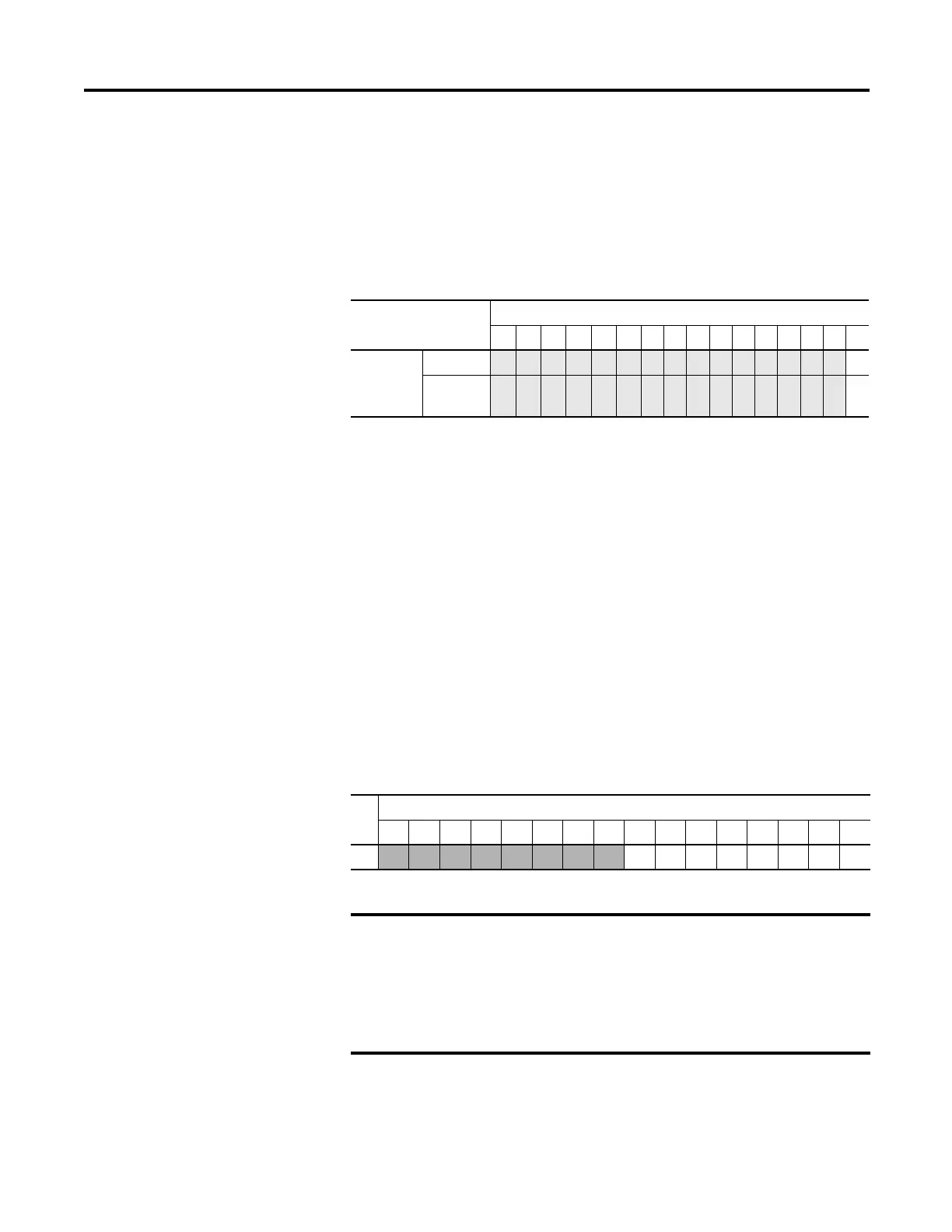
Module Configuration Word
Word 6 of the configuration data file contains the Enable/Disable Cyclic
Calibration bit.
1769-OA8
The following I/O memory mapping lets you configure the 1769-OA8 module.
Output Module’s Input Data File
For each module, slot x, input data file word 0 contains the state of the module’s
output data (output data echo) file word 0. During normal operation, these input
bits represent the logic state that the outputs are directed to by the control
program. They are also dependent upon these configurations:
• Program mode configuration, if supported by the controller
• Fault mode configuration, if supported by the controller
For the 1769-OA8, bits 8 to 15 are not used.
Program defaults are indicated by 0 values. For example, type J
thermocouple is the default (no user intervention) thermocouple type.
To select Make these bit settings
15 14 13 12 11 10 9 8 7 6 5 4 3 2 1 0
Enable/
Disable
Cyclic
Calibration
Enabled
(1)
(1) When enabled, an autocalibration cycle is performed on all enabled channels every 5 minutes.
0
Disabled
1
Word
Bit Position
1514131211109876543210
0
0 0 0 0 0 0 0 0r
(1)
(1) r = read.
rrrrrrr
The output module’s input data file reflects the output data echo of the
module, not necessarily the electrical state of the output terminals. It
does not reflect shorted or open outputs.
It is important to use this input word if the controller adapter supports
the Program mode or Fault mode function, and if it is configured to use
them.
 Loading...


