Rockwell Automation Publication 1769-IN088A-EN-P - February 2011 49
Module Wiring Chapter 2
External resistors are required if they are not internal to the encoder. The pull-up resistor (R) value
depends on the power supply value. To calculate the maximum resistor value, use this formula:
where:
· R = maximum pull-up resistor value
· Vdc = power supply voltage
· Vmin = 2.6V DC
· min = 6.8 mA
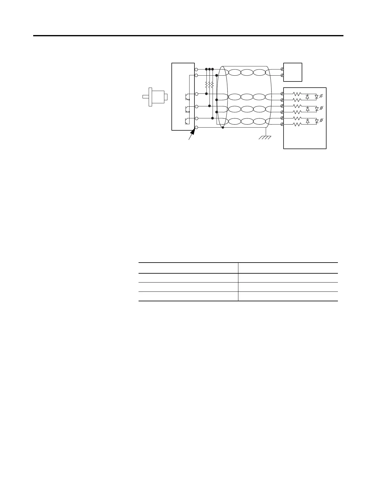
Single-ended Encoder Wiring
A
B
Z
A1(+)
A1(–)
B1(+)
B1(–)
Z1(+)
Z1(–)
GND
VS
+VDC
COM
R
(2)
Cable
Power
Supply
Allen-Bradley
845H Series
single-ended
encoder.
Shield/Housing
Connect only if housing is electronically
isolated from the motor and ground.
Shield
Module Inputs
Earth
Use twisted-pair, individually-shielded cable with
a maximum length of 300 m (1000 ft).
Power Supply Voltage
Pull-up Resistor Value Max (R)
(1)
(1) Resistance values may change, depending upon your application.
5V DC 352 Ω
12V DC 1382 Ω
24V DC 3147 Ω
R
V
dcVmin–()
Imin
--------------------------------------=
 Loading...


