Rockwell Automation Publication 1769-IN023C-EN-P - January 2022 5
CompactLogix 5370 L3 Controller Installation Instructions
Install the Secure Digital Card
The controller ships from the factory with the 1784-SD1 Secure Digital (SD) card installed.
1. Verify that the SD card is locked or unlocked according to your preference. Consider the following when deciding to lock the card before installation:
If the card is unlocked, the controller can write data to it or read data from it.
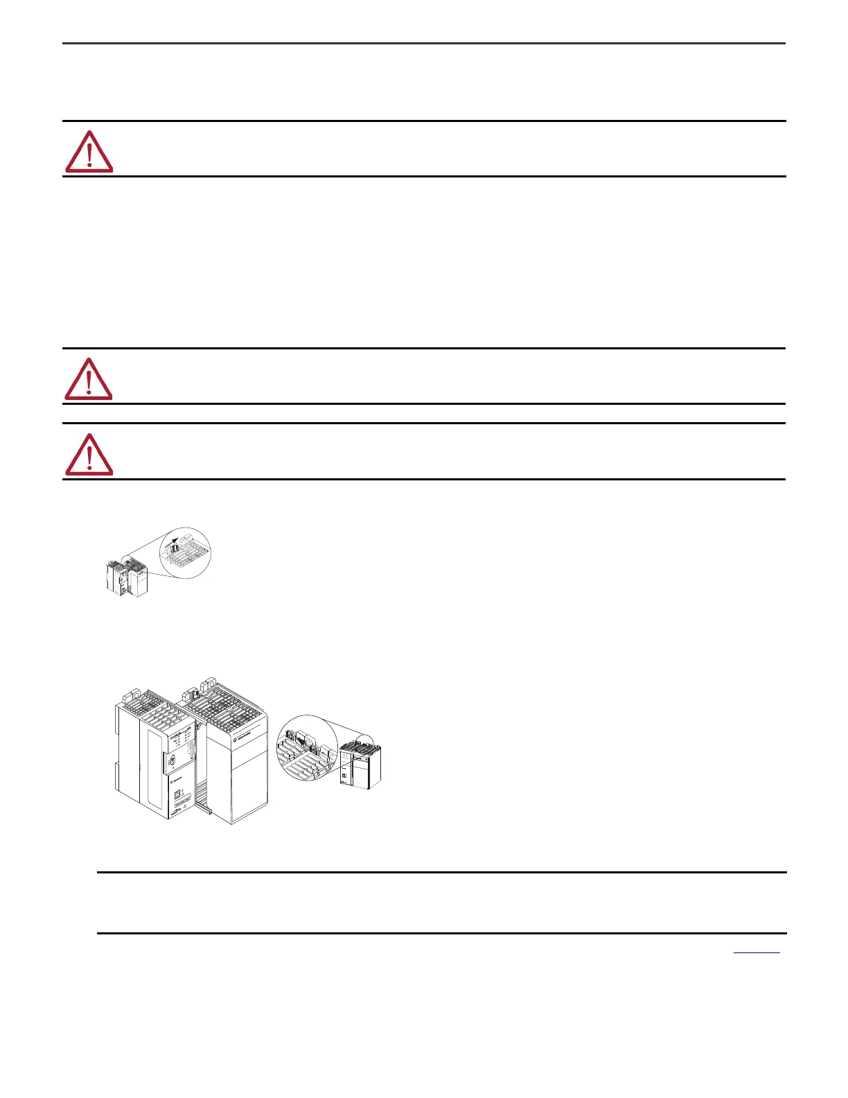
2. Open the door for the SD card.
3. Insert the SD card into the SD card slot, following the orientation logo that is printed on the card.
4. Gently press the card until it clicks into place.
5. Close the SD card door.
Assemble the System
1. Verify that line power is disconnected.
2. Make sure that the bus lever of the 1769 Compact I/O™ power supply is in the unlocked position, that is, leaning to the right.
3. Use the upper and lower tongue-and-groove slots to secure the controller and power supply together.
4. Move the power supply back along the tongue-and-groove slots until the bus connectors align with each other.
5. Use your fingers or a small screwdriver to push the bus lever on the power supply back slightly to clear the positioning tab.
6. Move the bus lever of the power supply fully to the left until it clicks; make sure that it locks.
7. If your system does not use any local expansion modules, use the tongue-and-groove slots described earlier to attach a 1769-ECR or 1769-ECRK Compact I/O end
cap terminator to the last module in the system.
8. Wire the 1769 Compact I/O power supply according to the directions in the Compact I/O Expansion Power Supplies Installation Instructions, publication 1769-IN028
.
WAR NIN G: When you insert or remove the SD card while power is on, an electric arc can occur. This could cause an explosion in hazardous location
installations.
Be sure that power is removed or the area is nonhazardous before proceeding.
ATTENTION: Do not remove or replace this module while power is applied. Interruption of the backplane can result in unintentional operation or
machine motion.
WAR NIN G: Remove power before removing or inserting this module. If you insert or remove the module while backplane power is on, an electric arc can
occur. This could cause an explosion in hazardous location installations.
Be sure that power is removed or the area is nonhazardous before proceeding.
IMPORTANT You must install an end cap onto the right side of the CompactLogix 5370 L3 controller system either at the end of the controller or at the
end of any local expansion modules that can be installed onto the controller.
The covering covers the exposed interconnections on the right side of the controller. Failure to use a protective covering could result in
equipment damage or injury from electric shock.

 Loading...


