Rockwell Automation Publication 20P-TD001K-EN-P - January 2021 39
PowerFlex DC Drive and Field Controller Technical Data
Frame D, Series B and C Heat Sink Cooling Fan Specifications
The frame D, series B and C drive cooling fan requires three-phase (50/60 Hz), 400…460V AC input power. If sourced
from the main three-phase AC input, the power supply connections must be taken from the primary side of the installed
isolation transformer or line reactor (clean power).
The cooling fan power input terminals U3, V3, and W3 are required to be short-circuit protected. This protection can be
provided by using a circuit breaker or fuses.
• If a circuit breaker is used, it must be rated for the short-circuit available current of the feeder source for this
circuit and the inrush current of the fan. Size the circuit breaker to help protect the wiring from the circuit
breaker connections to terminals U3, V3, and W3, and not spurious trip or blow from the inrush current.
• If fuses are used, they must be rated for either 400V AC, 2.5 amps (slow blow), or 460V AC, 3.15 amps (slow blow).
A normally closed (N.C.) contact wired to terminals 31 and 32 of the fan terminal block can be connected to an external device to provide
indication of a fan supply failure or can be wired to drive digital input terminals that are configured for 14 “Aux Fault” (via Pars 133…144).
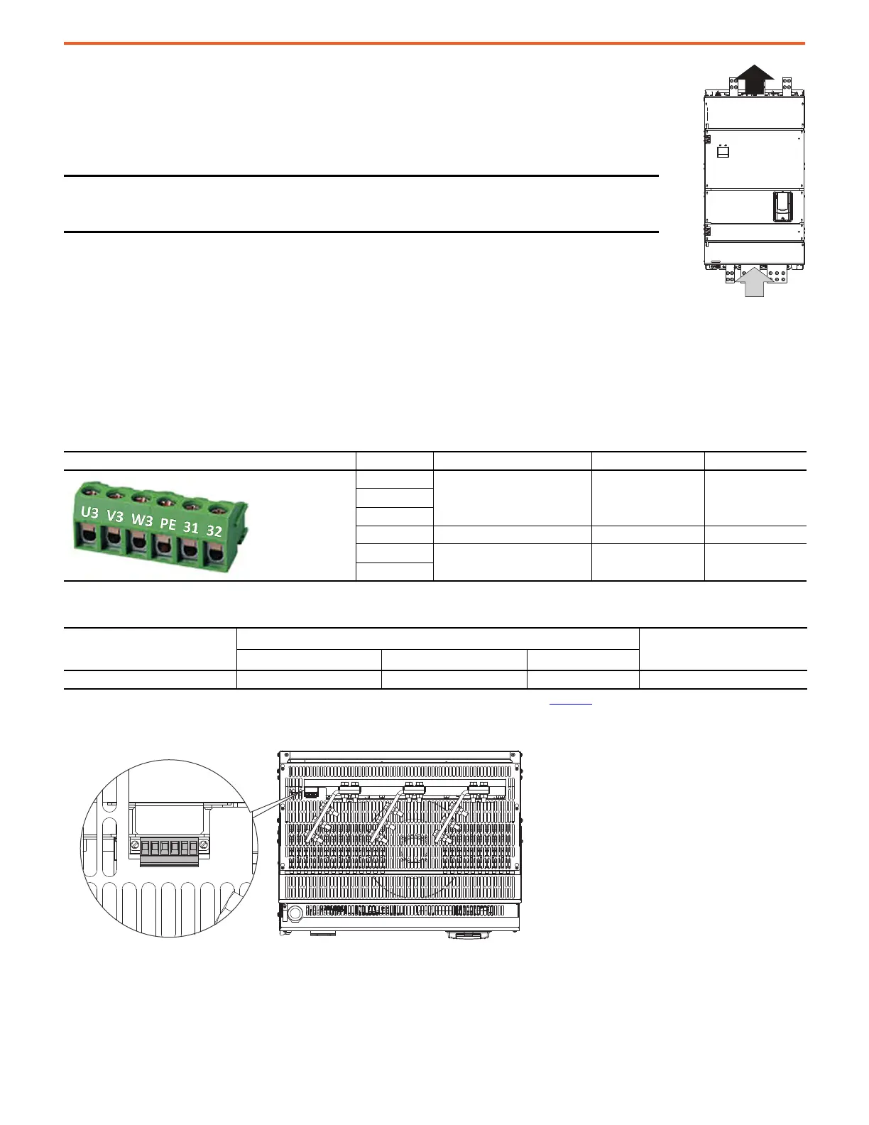
Frame D, Series B and C Heat Sink Cooling Fan Terminal Block Location
IMPORTANT When connecting the fan power wiring, verify that the airflow enters through the bottom
and exits through the top of the drive. If the airflow is incorrect, switch the leads on
terminals U3 and V3.
Frame D, Series B, and C Heat Sink Cooling Fan Terminal Designations
Terminal Block Terminal Description AC Voltage Max Current
U3
Three-phase AC input power
connections
400…460V AC
(50/60 Hz)
1.5 AV3
W3
PE Safety ground — —
31
Normally closed contact 250V AC 1 A
32
Frame D, Series B and C Heat Sink Cooling Fan Signal Wire Sizes and Terminal Specifications
Termi nal s
Wire Size and Type
(1)
(1) For more information, see Cable and Wiring Recommendations in the PowerFlex Digital DC Drive User Manual, publication 20P-UM001.
Tightening Torque
N•m (lb•in)
Flexible (mm
2
)Multicore (mm
2
)
AWG
U3, V3, W3, 31, 32, PE 0.14…1.5 0.14…2.5 28…12 0.5…0.6 (4.4…5.3)
U3 V3 W3 PE 31 32
U3 V3 W3 PE 31 32

 Loading...


