40 Rockwell Automation Publication 20P-TD001K-EN-P - January 2021
PowerFlex DC Drive and Field Controller Technical Data
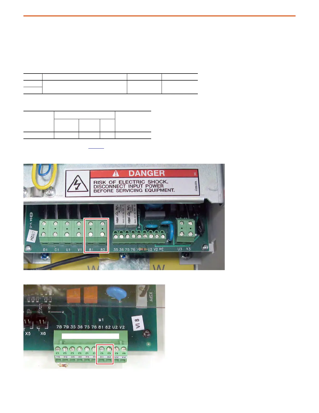
Frame C and D Armature Fuse Signal Terminals
Terminals 81 and 82 on frame C and D drives are connected to the internal armature circuit protection fuses and can be connected to an
external device to provide indication that the fuses have opened. Alternatively, terminals 81 and 82 can be wired to drive digital input
terminals that are configured for 64 “Invert Flt” (via Pars 133…144).
Frame C Internal Armature Fuse Signal Terminal Block Location
Frame D Internal Armature Fuse Signal Terminal Block Location
Armature Fuse Signal Terminal Designations
Terminal Description Maximum Voltage Maximum Current
81
Internal armature fuse intervention signal. 250V AC 1 A
82
Armature Fuse Signal Wire Size and Terminal Specifications
Terminals
Wire Size and Type
(1)
(1) For more information, see Cable and Wiring Recommendations in the PowerFlex
Digital DC Drive User Manual, publication 20P-UM001.
Tightening Torque
[N•m (lb•in)]
Flexible
[mm
2
]
Multicore
[mm
2
]
AWG
81, 82 0.14…1.5 0.14…2.5 26…16 0.4 (3.5)
On control pan to the left of the HIM

 Loading...


