30 Rockwell Automation Publication 20P-TD001K-EN-P - January 2021
PowerFlex DC Drive and Field Controller Technical Data
PowerFlex Field Controller Power Wiring Diagram Notes
1. For frame B field controllers only, a jumper is required between terminals SA and SB for 115V AC control input power. For more
information, see PowerFlex Field Controllers Power Wiring on page 24.
2. An isolation transformer and/or 3…5% impedance line reactor is required. If the isolation transformer provides the required 3…5%
impedance, a line reactor is not required. For recommendations, see PowerFlex DC Field Controller AC Input Line Reactors and AC
Contactors on page 16. It is recommended that the isolation transformer has a grounded wye secondary neutral. If the PowerFlex DC
field controller is installed in a system with an impedance ground connection, see Grounding for Installations in a Neutral Ground or
High Impedance System in the PowerFlex DC Field Controller Installation Instructions, publication 23PFC-IN001
.
3. AC input fuses (FS1) for the field converter are not provided with field controllers. For fuse recommendations, see Field Controller
Frames A and B AC Input Line Fuses on page 51.
4. Par 140 [Digital In8 Sel] set to 31 “Contactor.”
5. If the +24V internal power supply is used, terminal 18 (24V common) must be jumpered to terminal 35 (digital input common).
6. Par 1391 [ContactorControl] = 1 “AC Cntctr” and Par 1392 [Relay Out 1 Sel] = 25 “Contactor”. Important: Terminals 35 and 36 are on the
Control Power/Relay Outputs Terminal block, NOT the I/O terminal blocks. See Frames A and B Contact Relay and Thermistor Terminal
Block Locations on page 41.
7. For frames B field controllers only, a pilot relay is required for the contactor coil.
PowerFlex DC Drives Terminal Block Locations
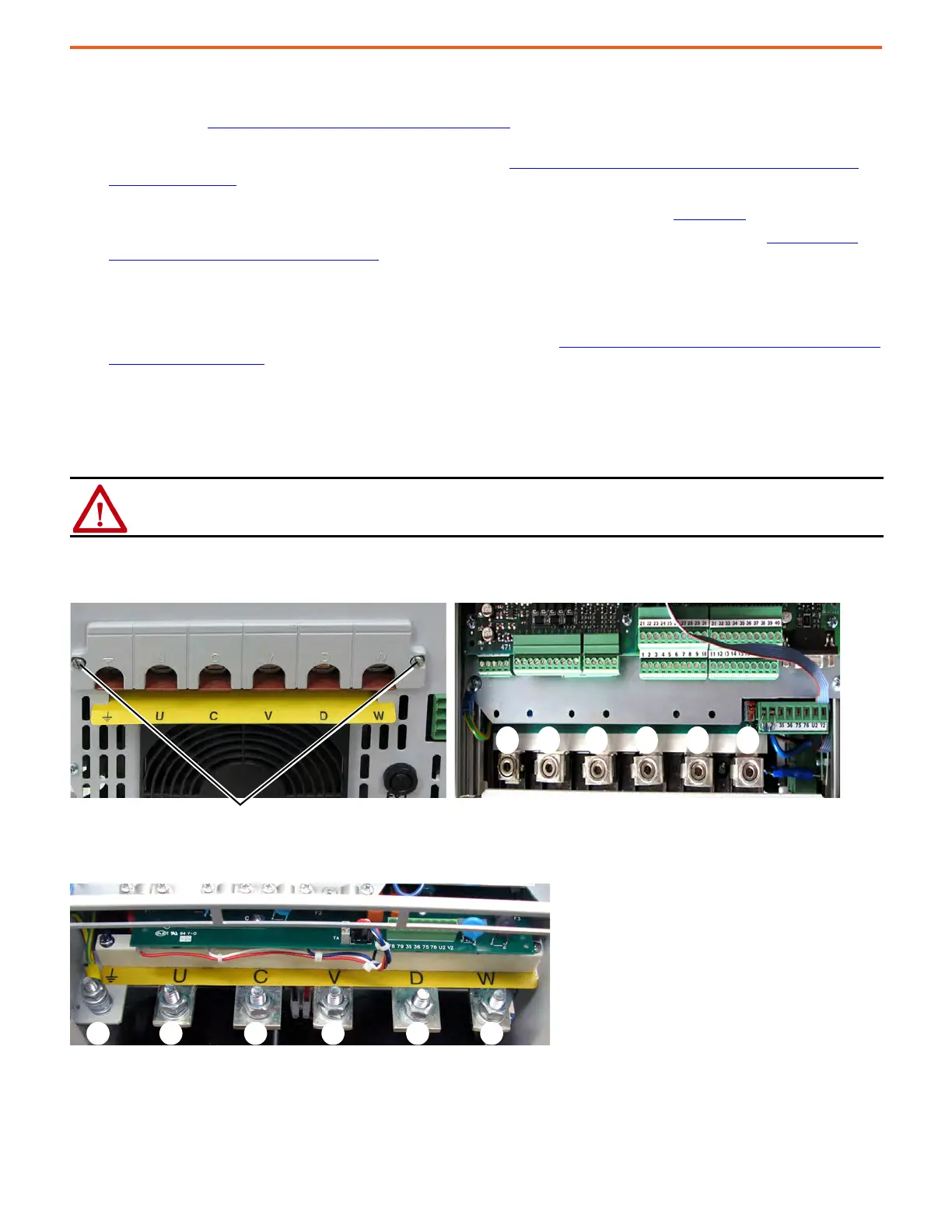
Frame A Armature Terminal Block Locations
Frame B Armature Terminal Block Locations
ATTENTION: Do not operate the drive with the power terminal cover removed. Operating the drive with the power terminal
cover removed can result in a hazardous condition that can cause personal injury and/or equipment damage.
Bottom View Front View
Front view of drive is shown with bottom protective and power terminal covers removed.Loosen the two screws that secure the power terminal cover to the drive chassis.
Remove the power terminal cover to connect the armature power wiring.
PE U C V D W

 Loading...


