Rockwell Automation Publication 20P-TD001K-EN-P - January 2021 45
PowerFlex DC Drive and Field Controller Technical Data
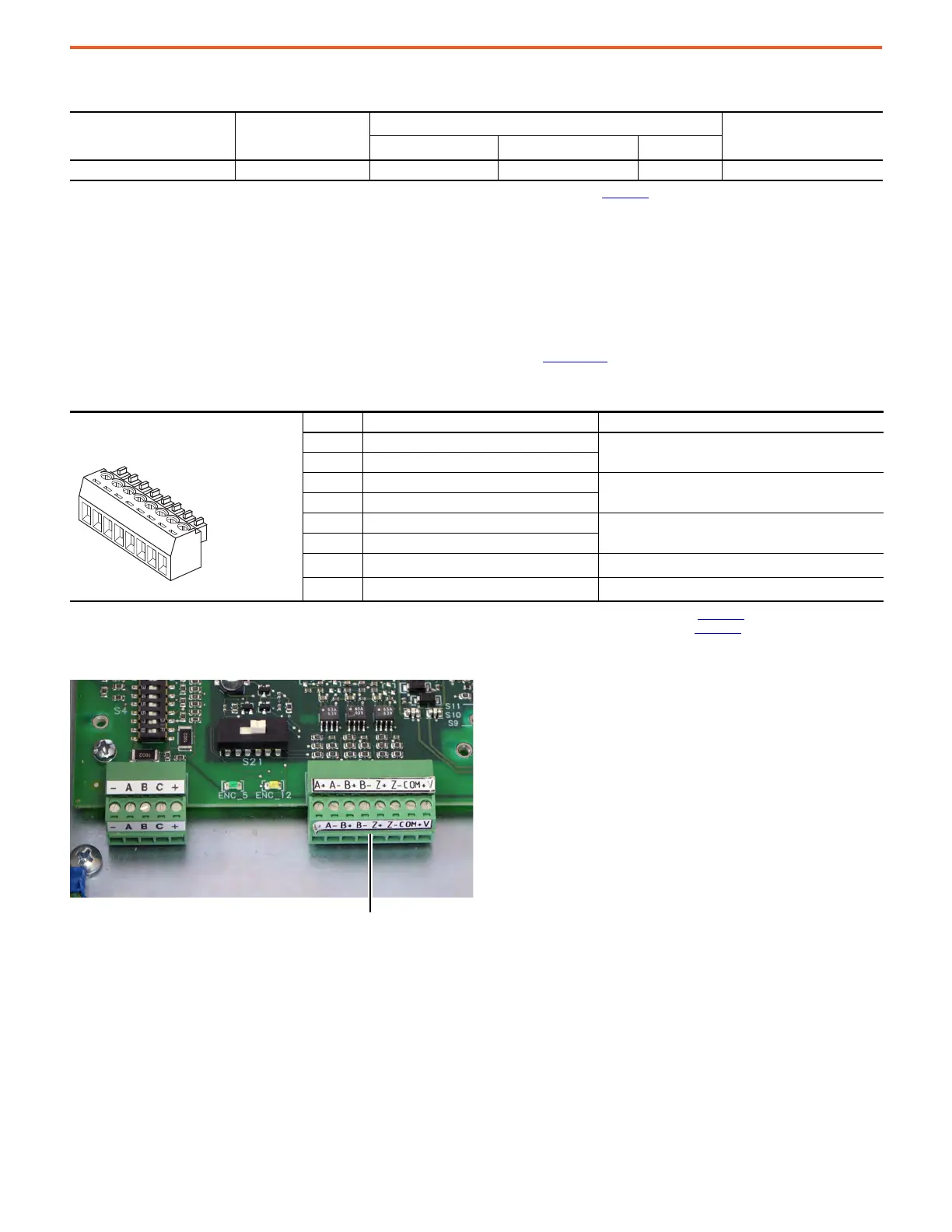
PowerFlex DC Drives Digital Encoder Terminal Block
Always connect the encoder connection cables directly to the terminals on the encoder terminal block. The encoder cable must be composed
of twisted pairs with the shield connected to the shield ground on the drive side. Do not connect the shield to ground on the motor side. In
some cases (that is, cable lengths that exceed 100 meters), it can be necessary to ground the shield of each twisted-pair on the power
supply. See Appendix A of the PowerFlex Digital DC Drive User Manual, publication 20P-UM001
, for Digital Encoder specifications.
Digital Encoder Terminal Block Location
Recommended Signal Wire Size for Analog I/O and Digital I/O
Signal Type
Terminal Block
(Terminals)
Wire Size and Type
(1)
(1) For more information, see Cable and Wiring Recommendations in the PowerFlex Digital DC Drive User Manual, publication 20P-UM001.
Tightening Torque
N•m (lb•in)
Flexible (mm
2
)Multicore (mm
2
)
AWG
Analog and Digital I/O TB1…4 (1…40) 0.140…1.500 0.140…1.500 26…16 0.4 (3.5)
Digital Encoder Terminal Designations
Terminal Block Label Signal Description
A+ Encoder A
Single ended or quadrature A input
A- Encoder A (NOT)
B+ Encoder B
Dual channel quadrature B input
B- Encoder B (NOT)
Z+ Encoder Z
Pulse, marker, or registration input
(1)
(1) Selectable via switch S20 on the Control board. See “DIP Switch and Jumper Settings” in the PowerFlex Digital DC Drive User Manual, publication 20P-UM001, for more information.
Z- Encoder Z (NOT)
COM
+5/12…15V
(2)
DC Return
Internal power common
+V
+5/12…15V
(2)
DC Power
(2) Selectable via switch S21 on the Control board. See “DIP Switch and Jumper Settings” in the PowerFlex Digital DC Drive User Manual, publication 20P-UM001, for more information.
Internal power source 200 mA
Digital Encoder terminal block

 Loading...


