EasyManuals Logo

Rockwell Automation Allen-Bradley PowerFlex 700 Series Service Manual

Rockwell Automation Allen-Bradley PowerFlex 700 Series
352 pages
To Next Page IconTo Next Page
To Previous Page IconTo Previous Page
Page #133 background imageLoading...
Page #133 background image
Rockwell Automation Publication 750-TG100B-EN-P - June 2019 133
Frame 7 Components Chapter 6
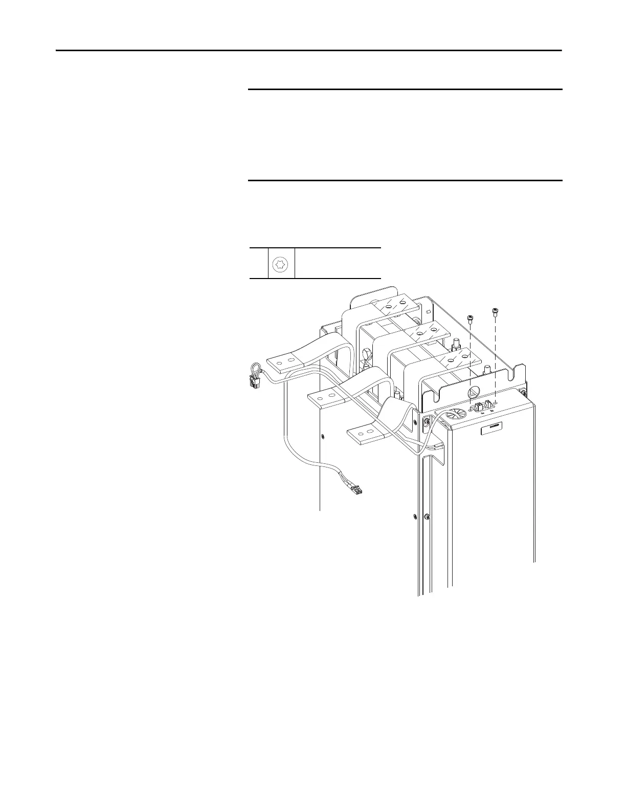
6. Remove the two M5 x 12 mm torx screws that secure the connector
mounting plate and connectors J1 and J2 to the protective cover on the
back of the LCL filter module.
IMPORTANT Connectors J1 and J2 are secured to a mounting plate on the underside
of the protective cover. You cannot remove the protective cover until
the mounting plate is removed.
The 24V DC control power wire harness is routed through a grommet in
the protective cover. You cannot remove the cover until the wire
harness is pulled through the back side of the grommet.
6
M5 x 12 mm
T25
2.6 N•m (23.0 lb•in)

Table of Contents

Other manuals for Rockwell Automation Allen-Bradley PowerFlex 700 Series

Questions and Answers:

Question and Answer IconNeed help?

Do you have a question about the Rockwell Automation Allen-Bradley PowerFlex 700 Series and is the answer not in the manual?

Rockwell Automation Allen-Bradley PowerFlex 700 Series Specifications

General IconGeneral
BrandRockwell Automation
ModelAllen-Bradley PowerFlex 700 Series
CategoryDC Drives
LanguageEnglish

Related product manuals