268 Rockwell Automation Publication 750-TG100B-EN-P - June 2019
Chapter 9 Power Bay Components
AC Common Mode Filter
Circuit Board Replacement
Replace the LCL filter module AC common mode filter circuit board with kit
catalog number SK-RM-EMCFB1.
Remove the AC Common Mode Filter Circuit Board
Follow these steps to remove and replace the AC common mode filter circuit
board.
1. Review the Product Advisories on page 14
.
2. Remove power from the system. See Remove Power from the System on
page 15
.
3. Open the corresponding power bay enclosure door.
4. Remove the LCL filter module from the enclosure. See LCL Filter Module
Replacement on page 257
.
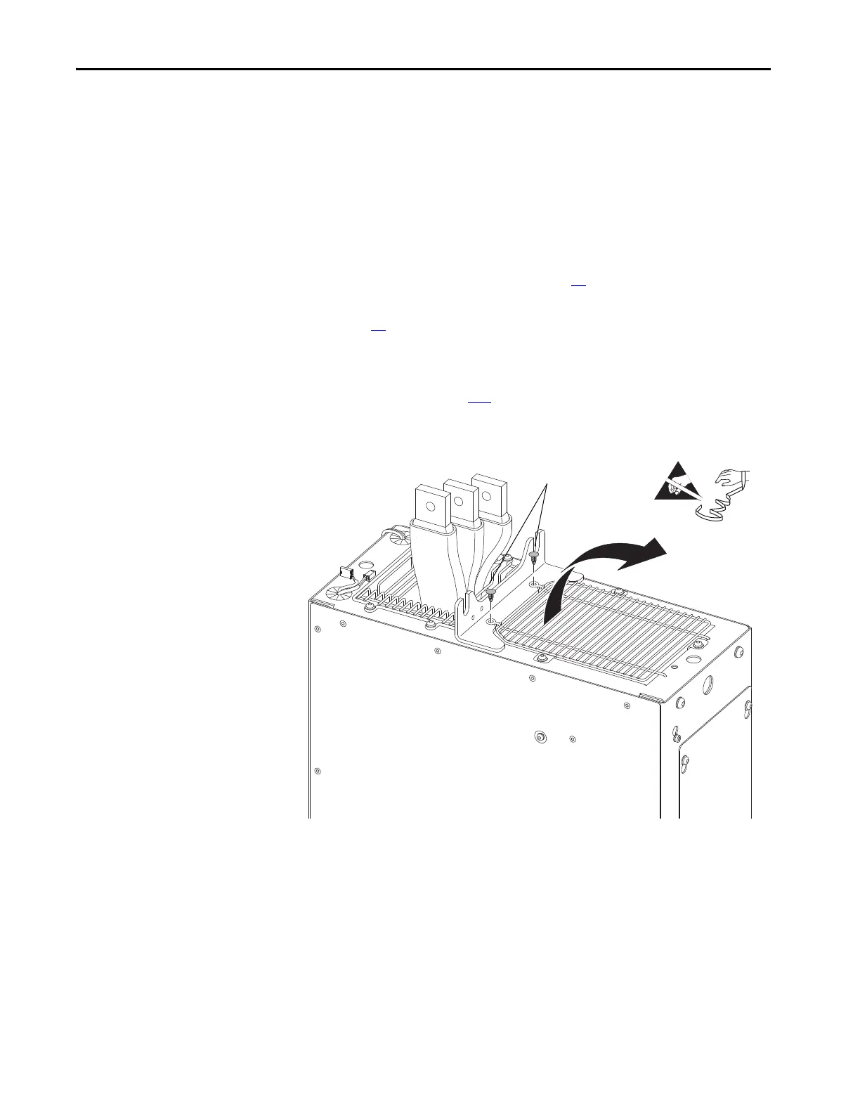
5. Remove the two barb fasteners that secure the screen to the chassis and
remove the screen. The barb fasteners are not reusable.
 Loading...


