EasyManuals Logo

Rockwell Automation Allen-Bradley PowerFlex 700 Series Service Manual

Rockwell Automation Allen-Bradley PowerFlex 700 Series
352 pages
To Next Page IconTo Next Page
To Previous Page IconTo Previous Page
Page #183 background imageLoading...
Page #183 background image
Rockwell Automation Publication 750-TG100B-EN-P - June 2019 183
Input Bay Components Chapter 8
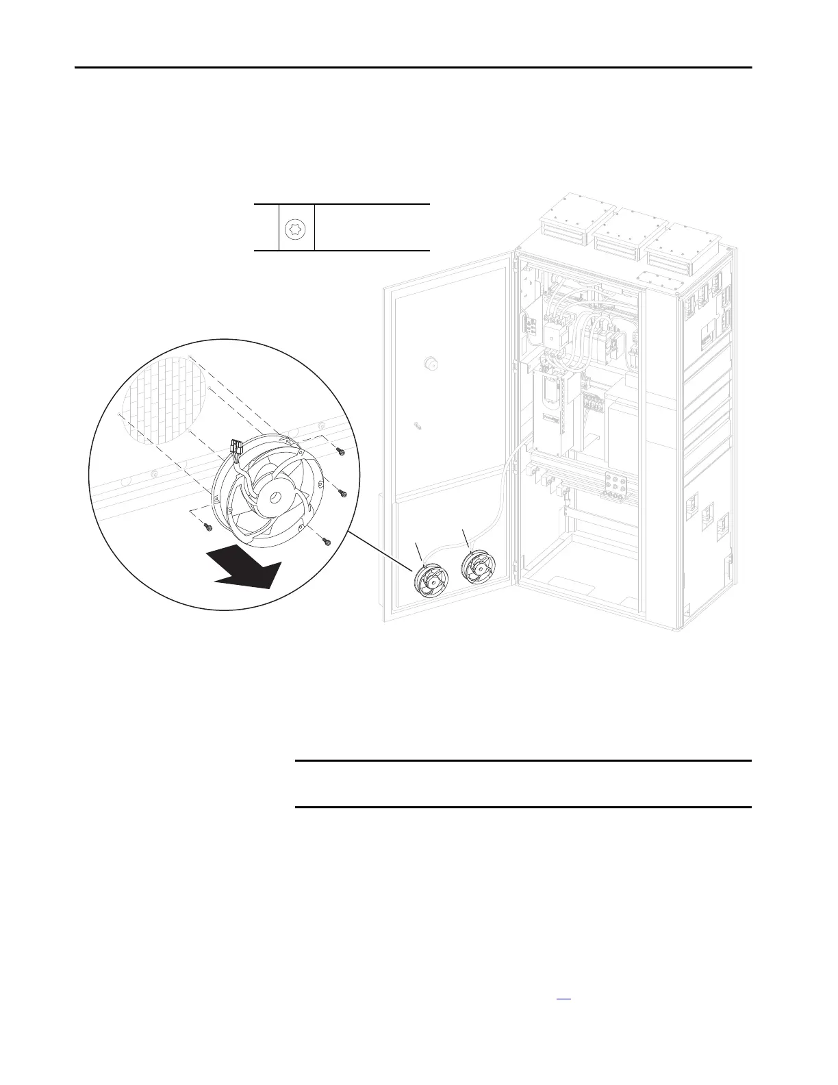
3. Open the input bay enclosure door.
4. Disconnect the connectors P12 or P13 from the fans on the door.
5. Remove the four M4 x 14 mm torx screws that secure the fan to the door
and remove the fan.
Install the IP21/IP54, 1000 mm Wide Door Vent Fan
Follow theses steps to install the IP21/IP54, 1000 mm wide door vent fan.
Guard Removal
You must remove the guards to access other components inside the input bay.
Remove the Guards
Follow these steps to remove and replace the guards.
1. Review the Product Advisories on page 14
.
P12
P13
5
M4 x 14 mm
T20
2.6 N
•m (23 lb•in)
IMPORTANT Verify that the airflow direction arrow on the fan points inward, toward the
interior of the enclosure.

Table of Contents

Other manuals for Rockwell Automation Allen-Bradley PowerFlex 700 Series

Questions and Answers:

Question and Answer IconNeed help?

Do you have a question about the Rockwell Automation Allen-Bradley PowerFlex 700 Series and is the answer not in the manual?

Rockwell Automation Allen-Bradley PowerFlex 700 Series Specifications

General IconGeneral
BrandRockwell Automation
ModelAllen-Bradley PowerFlex 700 Series
CategoryDC Drives
LanguageEnglish

Related product manuals