EasyManuals Logo

Rockwell Automation Allen-Bradley PowerFlex 700 Series Service Manual

Rockwell Automation Allen-Bradley PowerFlex 700 Series
352 pages
To Next Page IconTo Next Page
To Previous Page IconTo Previous Page
Page #274 background imageLoading...
Page #274 background image
274 Rockwell Automation Publication 750-TG100B-EN-P - June 2019
Chapter 9 Power Bay Components
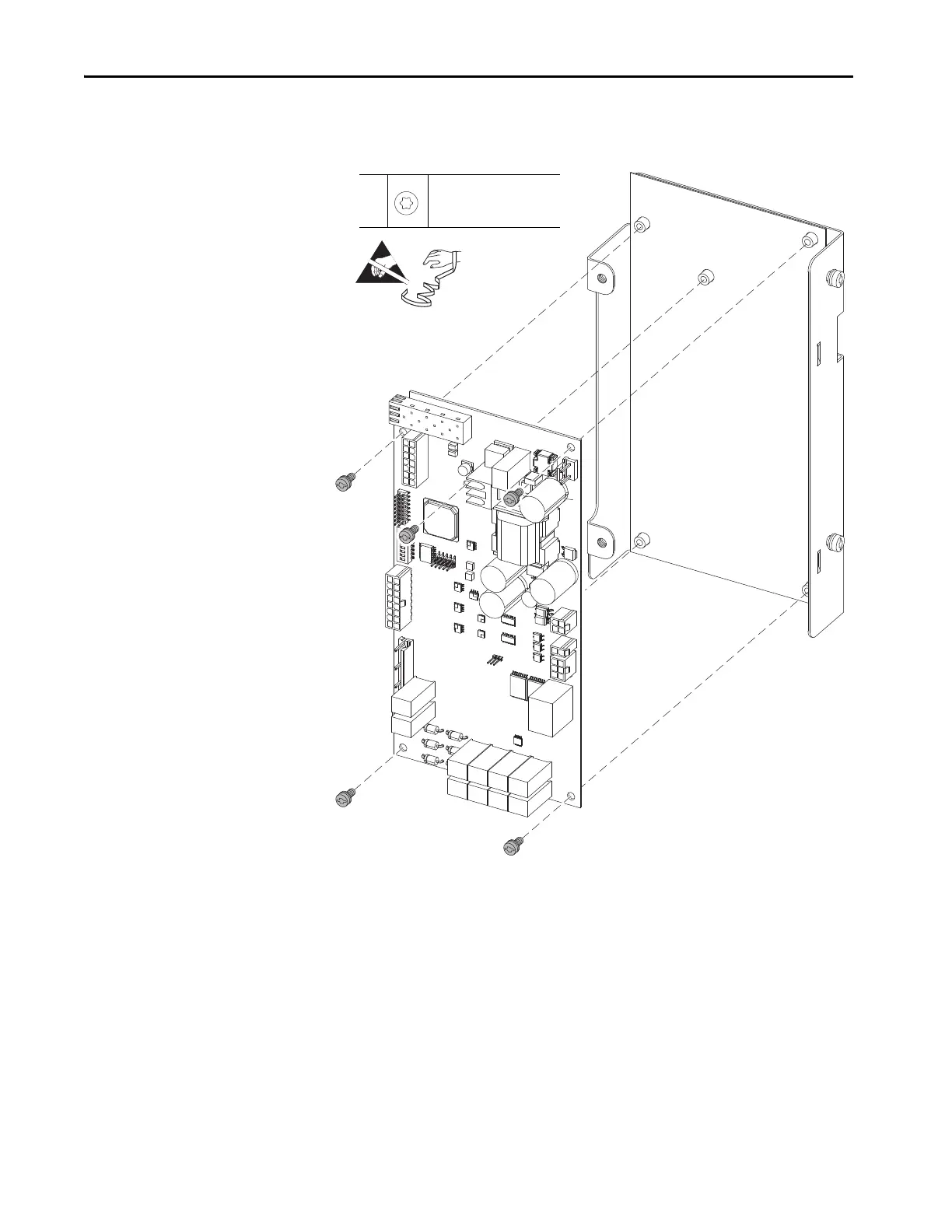
14. Remove the five M4 x 8 mm torx screws that secure the current sense
circuit board to the circuit board tray and remove the circuit board.
Install the Current Sense Circuit Board
Install the current sense circuit board in the reverse order of removal.
1. Secure the wires to the circuit board tray by using cable ties in the same
locations as previously secured.
2. When installing the fiber-optic cables:
14
M4 x 8 mm
T25
1.8 N•m (15.5 lb•in)
=

Table of Contents

Other manuals for Rockwell Automation Allen-Bradley PowerFlex 700 Series

Questions and Answers:

Question and Answer IconNeed help?

Do you have a question about the Rockwell Automation Allen-Bradley PowerFlex 700 Series and is the answer not in the manual?

Rockwell Automation Allen-Bradley PowerFlex 700 Series Specifications

General IconGeneral
BrandRockwell Automation
ModelAllen-Bradley PowerFlex 700 Series
CategoryDC Drives
LanguageEnglish

Related product manuals