EasyManuals Logo

Rockwell Automation Allen-Bradley PowerFlex 700 Series Service Manual

Rockwell Automation Allen-Bradley PowerFlex 700 Series
352 pages
To Next Page IconTo Next Page
To Previous Page IconTo Previous Page
Page #51 background imageLoading...
Page #51 background image
Rockwell Automation Publication 750-TG100B-EN-P - June 2019 51
Component Inspection and Test Procedures Chapter 3
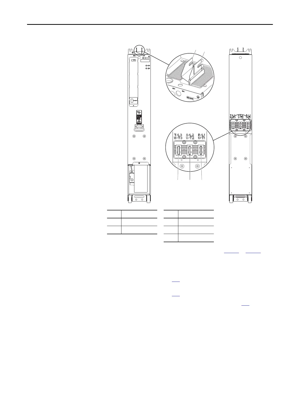
Figure 7 - Frames 8…15 Power Module Power Terminal Locations
5. If the product fails the measurements identified in Tab le 6 or Tab le 7, take
the appropriate action:
• For frames 5 and 6, replace the drive or bus supply.
• For frames 7, replace the power module. See Power Module
Replacement on page 113
.
• For frames 8…15, replace the power module. See Power Module
Replacement on page 236
.
6. Complete the procedures in Chapter 11 - Chapter on page 291
before
placing the drive back into service.
ID Connection ID Connection
1 +DC 3 R/L1, U/T1
2 –DC 4 S/L2, V/T2
5 T/L3, W/T3
1
2
543

Table of Contents

Other manuals for Rockwell Automation Allen-Bradley PowerFlex 700 Series

Questions and Answers:

Question and Answer IconNeed help?

Do you have a question about the Rockwell Automation Allen-Bradley PowerFlex 700 Series and is the answer not in the manual?

Rockwell Automation Allen-Bradley PowerFlex 700 Series Specifications

General IconGeneral
BrandRockwell Automation
ModelAllen-Bradley PowerFlex 700 Series
CategoryDC Drives
LanguageEnglish

Related product manuals