124 Rockwell Automation Publication 750-RM100A-EN-P - August 2019
Chapter 11 Application References
Variable Frequency
In this configuration, one reference notch filter is set dynamically as the length of
the cable changes. This approach requires hardware interconnection. The
encoder feedback from the Z (hoist) drive is connected to a Logix controller.
This feedback is used to calculate instantaneous cable length, then the length is
used to calculate the instantaneous filter frequency. The trolley and/or gantry
drives are also connected to the controller via datalinks. The instantaneous filter
frequency is then sent to the reference notch filter in these drives.
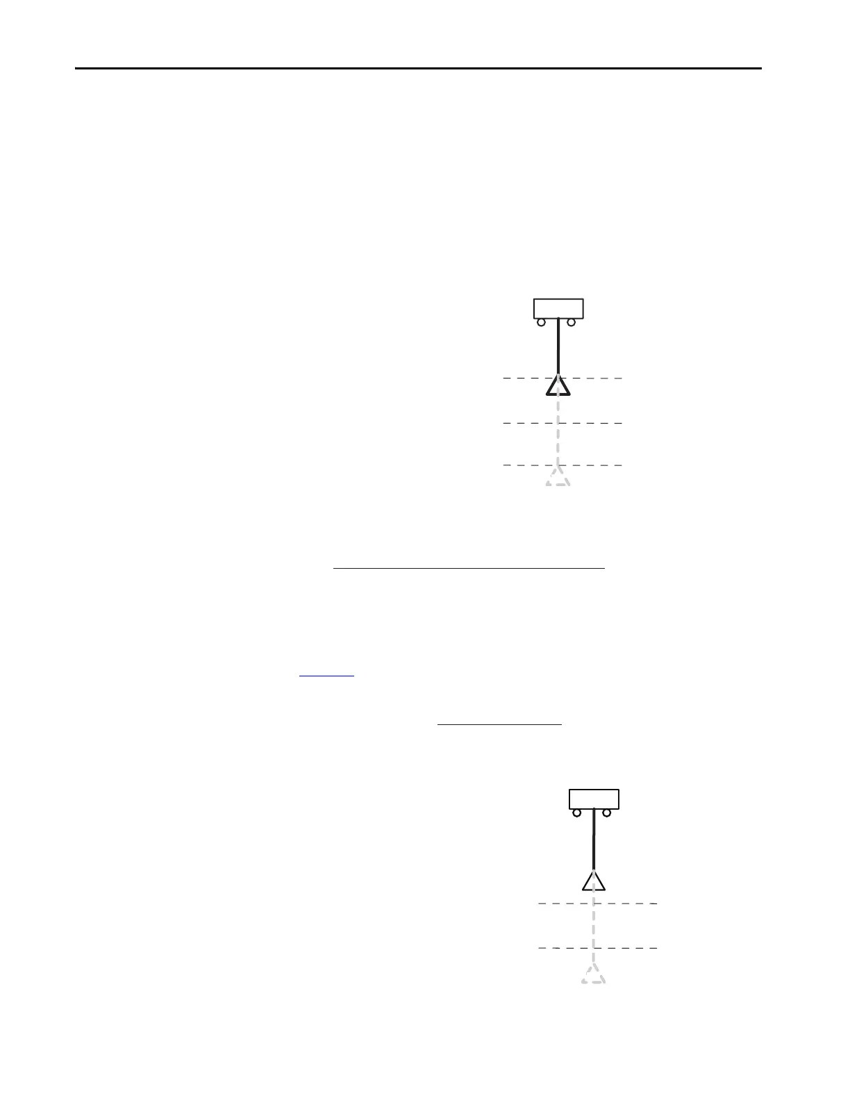
Figure 48 - Variable Frequency Configuration
To calculate the cable length from hoist drive encoder feedback, we can assume a
linear relationship between the cable length (L) and the encoder counts (x), as:
To find the Conversion Constant (Equation 6), two given points are required:
L1and L2 which can be obtained by measuring the cable length at two arbitrary
points and capturing the corresponding hoist encoder counts, as shown in
Figure 49
. The Offset encoder counts are determined via a homing routine or an
absolute encoder feedback position. Therefore:
Figure 49 - Relationship Between Hoist Encoder Counts and Cable Length
L =
Current Encoder Counts - Offset Encoder Counts
Conversion Constant
Conversion Constant =
L1 - L2
Delta Length Change
C
orresponding to x
1
counts,
L
1
C
orresponding to x
2
counts,
L
2
 Loading...


