Rockwell Automation Publication 750-RM100A-EN-P - August 2019 21
AC Line Tuning Chapter 2
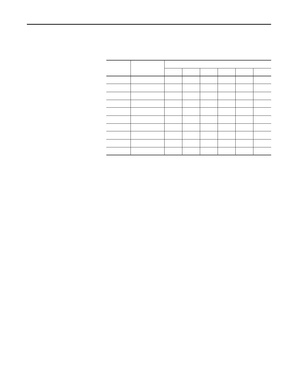
thresholds for the additional modules that are based on frame size. Table cells
with a dash indicate that the frame does not have that LCL module installed.
Voltage Regulator Gains—Manual Adjustment
PowerFlex 755T products allow individual manual adjustment of the
proportional and integral terms that are used by the voltage regulator. To enable
manual adjustment of the proportional and integral terms, set 13:54 [Volt Reg
C/U Sel] to 1 ‘User Entered’. This setting switches the gains that are used by the
voltage regulator from the calculated values to values that are entered in
parameters 13:57 [u Volt Reg Kp] and 13:59 [u Volt Reg Ki].
It is recommended to begin manual adjustment with the suggested gain start
points. To initiate the transfer of these values, toggle 13:54 [Volt Reg C/U Sel] to
2 ‘LoadCalcData’. When this option is selected, the calculated gains values are
copied to the user entered gain parameters. When the transfer is complete, 13:54
[Volt Reg C/U Sel] will automatically set to 1 ‘User Entered’ for manual
adjustment.
Proper adjustment of the individual proportional and integral terms is more
difficult than adjusting the bandwidth because the ideal spacing between the
proportional and integral terms is not maintained. The theoretical ideal spacing
between the proportional and integral terms is where Z = 1 is the desired
damping factor. This creates a 4:1 spacing.
Table 6 - Resonance Current Thresholds
LCL Module Parameters Resonance Current by Frame 400V/480V (600V/690V) [A]
10 11 12 13 14 15
0 14:1216…14:1218 82 (62) 82 (62) 82 (62) 82 (62) 82 (62) 82 (62)
1 14:1316…14:1318——————
2 14:1416…14:1418 41 (31) 82 (62) 82 (62) 41 (31) 82 (62) 82 (62)
3 14:1516…14:1518———82 (62)——
4 14:1616…14:1618 — — 41 (31) — 82 (62) 41 (31)
5 14:1716…14:1718———41 (31)—82 (62)
6 14:1816…14:1818————82 (62)—
7 14:1916…14:1918—————82 (62)
8 14:2016…14:2018——————
9 14:2116…14:2118—————41 (31)
 Loading...


