14 Rockwell Automation Publication PFLEX-AP005A-EN-P - October 2010
Chapter 1 Drive Selection Considerations
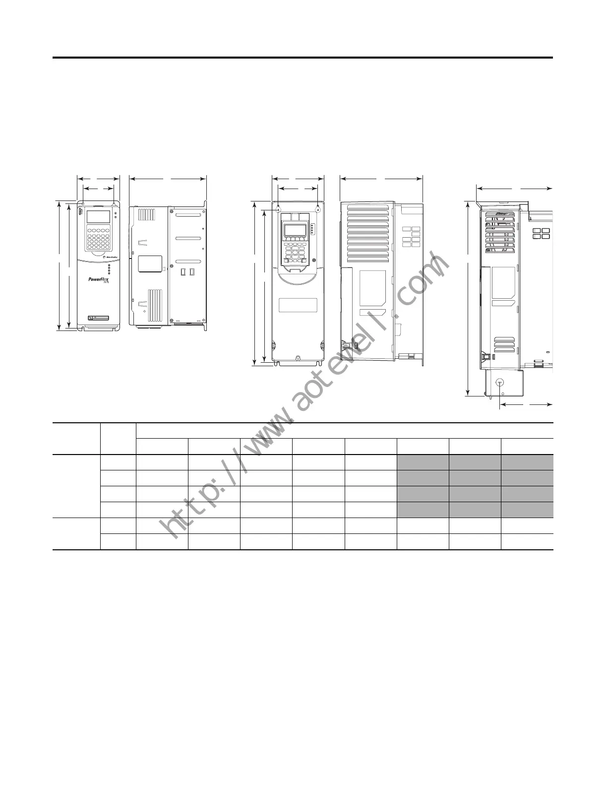
Dimensions
Figure 2 - PowerFlex 700 Frames 0…3 to PowerFlex 750-Series Frames 2 & 3
Dimensions mm (in.)
DriveFrameABCDE FGH
700 0 110.0 (4.33) 80.0 (3.15) 200.0 (7.87) 336.0 (13.23) 320.0 (12.60)
1 135.0 (5.32) 105.0 (4.13) 200.0 (7.87) 336.0 (13.23) 320.0 (12.60)
2 222.0 (8.74) 192.0 (7.56) 200.0 (7.87) 342.5 (13.48) 320.0 (12.60)
3 222.0 (8.74) 192.0 (7.56) 200.0 (7.87) 517.5 (20.37) 500.0 (19.69)
750-Series 2 134.5 (5.30) 100.0 (3.94) 212.0 (8.35) 424.2 (16.70) 404.2 (15.91) 222.2 (8.75) 497.1 (19.57) 38.0 (1.50)
3 190.0 (7.48) 158.0 (6.22) 212.0 (8.35) 454.0 (17.87) 435.0 (17.13) 223.1 (8.78) 530.1 (20.87) 38.0 (1.50)
C
A
B
E
D
HOT surfaces can cause severe burns
CAUTION
C
A
B
E
D
F
H
G
PowerFlex 700 Frames 0…3
(Frame 0 shown)
PowerFlex 750-Series Frames 2 & 3
(Frame 2 shown)
PowerFlex 750-Series
2 & 3 w/NEMA 1 Kit
(Frame 2 shown)
 Loading...


