Rockwell Automation Publication PFLEX-AP005A-EN-P - October 2010 37
Drive Selection Considerations Chapter 1
5
6
(1)
7
(2)
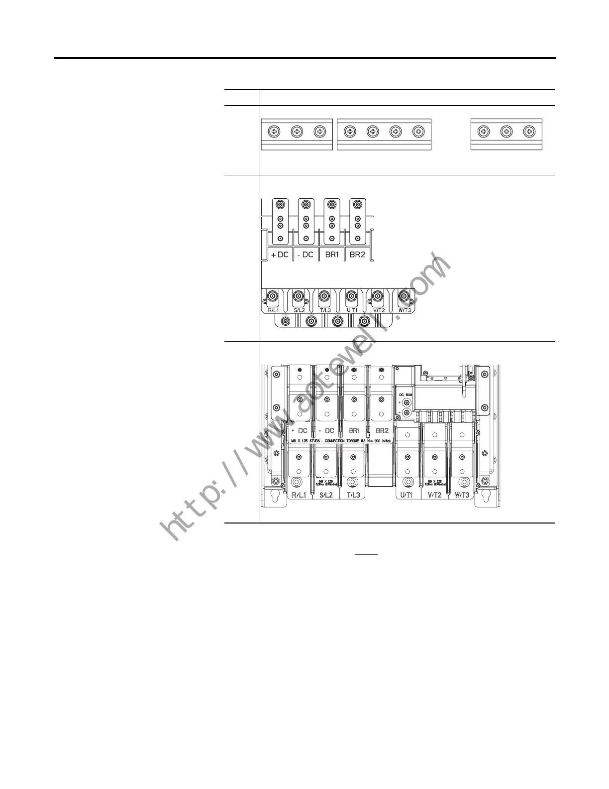
(1) DC Bus Terminals are optional on Frame 6 and 7 drives: catalog number position 5.
(2) Dynamic Brake Resistor Terminals are optional on Frame 6 and 7 drives: catalog number position 12.
Refer to Catalog Number Explanation on page 46
.
Frame Power Terminal Blocks
L1
R
L2
S
L3
T
BR1 BR2 +DC -DC T1
U
T2
V
T3
W
L1
R
L2
S
L3
T
GND GND GNDGND
T1
U
T2
V
T3
W
BR1 BR2+DC -DC
BR1 BR2+DC -DC
L1
R
L2
S
L3
T
T1
U
T2
V
T3
W
 Loading...


