Rockwell Automation Publication PFLEX-AP005A-EN-P - October 2010 47
Drive Selection Considerations Chapter 1
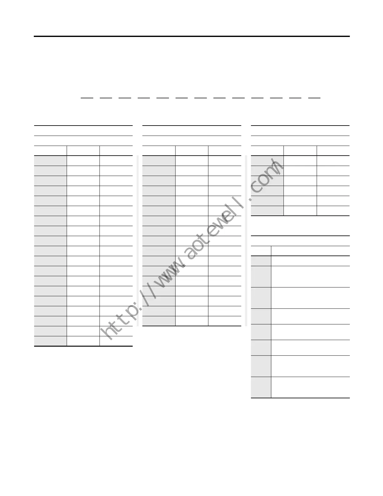
Table 4a- PowerFlex 700 Drive Catalog Number Explanation (continued)
Position
1 - 3
a
20B
4
b
D
5 - 7
c
2P1
8
d
A
9
e
3
10
f
A
11
g
Y
12
h
N
13
i
A
14
j
R
15
k
C
16
l
0
17 - 18
m
NN
19 - 20
n
AD
c5
ND Rating
690V, 50 Hz Input
Code Amps kW
052 52 45
060 60 55
082 82 75
098 98 90
119 119 110
142 142 132
c3
ND Rating
480V, 60 Hz Input
Code Amps Hp
1P1 1.1 0.5
2P1 2.1 1
3P4 3.4 2
5P0 5.0 3
8P0 8.0 5
011 11 7.5
014 14 10
022 22 15
027 27 20
034 34 25
040 40 30
052 52 40
065 65 50
077 77 60
096 96 75
125 125 100
156 156 125
180 180 150
248 248 200
c4
ND Rating
600V, 60 Hz Input
Code Amps Hp
1P7 1.7 1
2P7 2.7 2
3P9 3.9 3
6P1 6.1 5
9P0 9.0 7.5
011 11 10
017 17 15
022 22 20
027 27 25
032 32 30
041 41 40
052 52 50
062 62 60
077 77 75
099 99 100
125 125 125
144 144 150
d
Enclosure
Code Description
A IP20, NEMA/UL Type 1
F
(1)
(1) Only available for Frame 5 and Frame 6 drives,
400V…690V.
(2) Only available for Frames 7…10 drives.
(3) Only available with vector control option.
(4) Only available for Frame 8 and Frame 9 drives.
Open/Flange mount
Front: IP00, NEMA/UL Type Open
Back/Heatsink: IP54, NEMA Type 12
N
(2)
Open/Flange mount
Front: IP00, NEMA/UL Type Open
Back/Heatsink: IP54, NEMA 12
G
(1)
Stand-alone/Wall mount
IP54, NEMA/UL Type 12
J IP00, NEMA/UL Type Open
with conformal coat
M
(3)
IP20, NEMA/UL Type 1
with conformal coat
U
(4)
Roll-in
Front: IP00, NEMA/UL Type Open
Back/Heatsink: IP54, NEMA 12
V
(4)
Roll-in with conformal coat
Front: IP00, NEMA/UL Type Open
Back/Heatsink: IP54, NEMA 12
 Loading...


