50 Rockwell Automation Publication PFLEX-AP005A-EN-P - October 2010
Chapter 1 Drive Selection Considerations
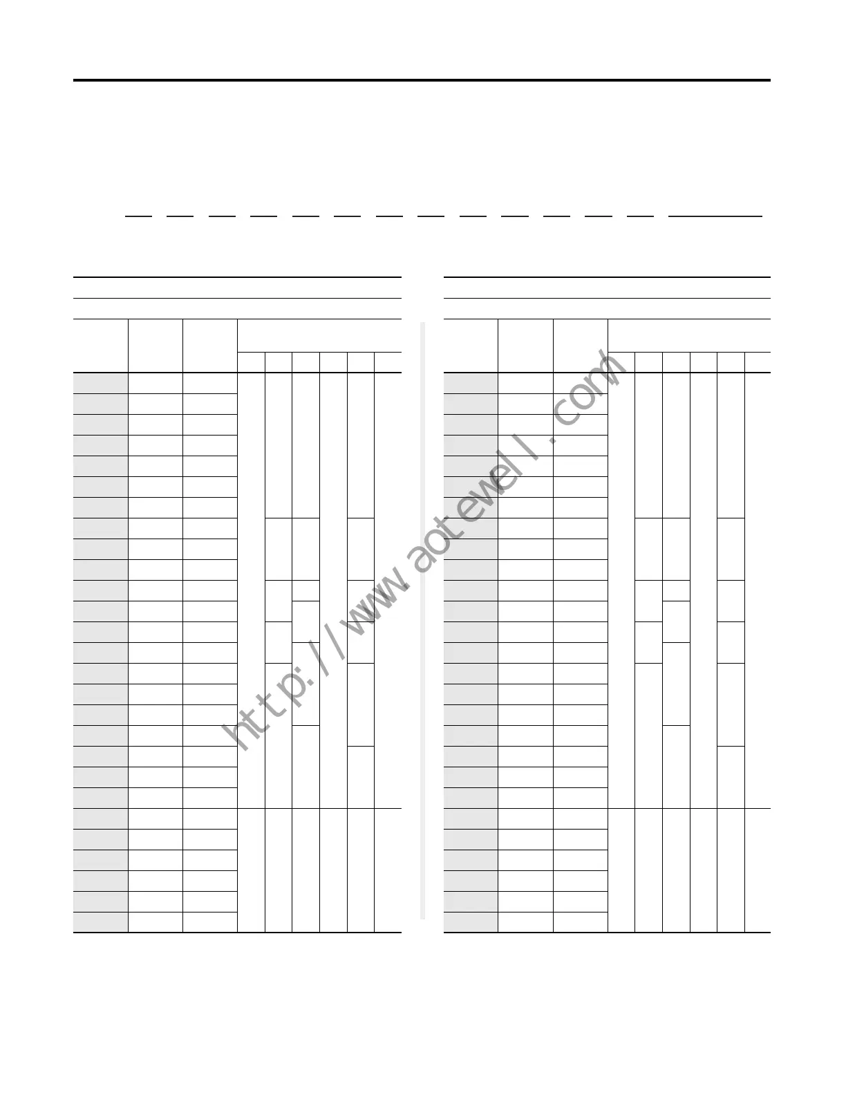
Table 5a- PowerFlex 750-Series Drive Catalog Number Explanation (continued)
f2
ND Rating
480V, 60 Hz Input
Frame Available Based
On Enclosure Code
Code Amps Hp B F G L N P
2P1 2.1 1
—
22
—
2
—
3P4 3.4 2
5P0 5.0 3
8P0 8.0 5
011 11 7.5
014 14 10
022 22 15
027 27 20
33 3
034 34 25
040 40 30
052 52 40
4
4
4
065 65 50
5
077 77 60
55
096 96 75
6
125 125 100
(1)
(1) For Frame 6 & 7 drives: a user-installed flange kit is available to convert a
code N drive that provides a NEMA/UL Type 4X/12 back.
6
156 156 125
186 186 150
248 248 200
7
302 302 250
7
361 361 300
415 415 350
430 430 350
8——8—
8
(2)
(2) Available as a drive with cabinet options (21G). MCC power bus is not UL
listed.
485 485 400
545 545 450
617 617 500
710 710 600
740 740 650
Position
1 - 3
a
20F
4
b
1
5
c
1
6
d
N
7
e
D
8 - 10
f
248
11
g
A
12
h
A
13
i
0
14
j
N
15
k
N
16
l
N
17
m
N
18
n
N
21G Cabinet Options
- LD - P3 - P11...
f1
ND Rating
400V, 50 Hz Input
Frame Available Based
On Enclosure Code
Code Amps kW B F G L N P
2P1 2.1 0.75
—
22
—
2
—
3P5 3.5 1.5
5P0 5.0 2.2
8P7 8.7 4.0
011 11.5 5.5
015 15.4 7.5
022 22 11
030 30 15
33 3
037 37 18.5
043 43 22
060 60 30
4
4
4
072 72 37
5
085 85 45
55
104 104 55
6
140 140 75
(1)
(1) For Frame 6 & 7 drives: a user-installed flange kit is available to convert a
code N drive that provides a NEMA/UL Type 4X/12 back.
6
170 170 90
205 205 110
260 260 132
7
302 302 160
7
367 367 200
456 456 250
460 460 250
8——8—
8
(2)
(2) Available as a drive with cabinet options (21G). MCC power bus is not UL
listed.
540 540 315
567 567 315
650 650 355
750 750 400
770 770 400
 Loading...


