58 Rockwell Automation Publication PFLEX-AP005A-EN-P - October 2010
Chapter 2 Analog Speed Follower and Preset Speed
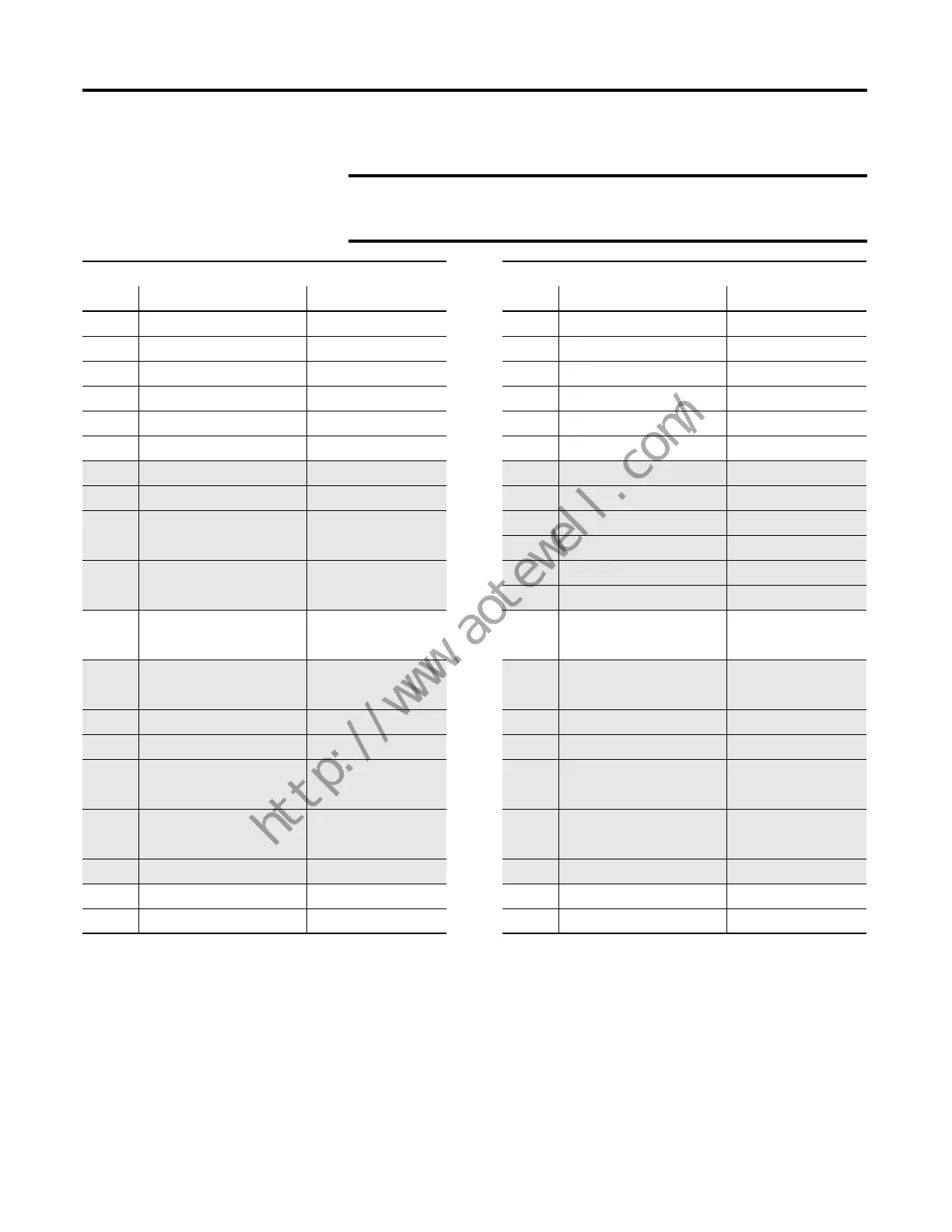
Table 30 - PowerFlex 700 to PowerFlex 750-Series Drive (using optional I/O module)
IMPORTANT
Shaded table cells indicate factory-set default settings. Please verify
these settings if the drive is not new or a “set to factory defaults” was
never performed.
PowerFlex 700 Drive Parameters PowerFlex 750-Series Drive Parameters
(1)
No. Name Value No. Name Value
41 Motor NP Volts 460 25 Motor NP Volts 460
42 Motor NP Amps 1.6 26 Motor NP Amps 1.6
43 Motor NP Hertz 60 27 Motor NP Hertz 60
44 Motor NP rpm 1785 28 Motor NP rpm 1785
45 Motor NP Power 1 30 Motor NP Power 1
46 Motor NP Power Units 0-Hp 29 Motor NP Power Units 0-Hp
49 Motor Poles 4 31 Motor Ctrl Mode 1-Induction SV
79 Speed Units 0-Hz 300 Speed Units 0-Hz
81 Minimum Speed 0.0 522
(2)
Min Fwd Speed 0.0
523
(2)
Min Rev Speed 0.0
82 Maximum Speed 60.0 520
(2)
Max Fwd Speed Motor NP Hz/rpm x 1
521
(2)
Max Rev Speed Motor NP Hz/rpm x -1
90 Speed Ref A Sel 1-Analog In 1 545 Spd Ref A Sel Port 4 (P50)
Spd Ref A
91 Speed Ref A Hi Max Speed (P82) 547 AnlgHi Max Fwd Spd (P520)
Spd Ref A
92 Speed Ref A Lo 0.0 548 AnlgLo 0.0
140 Accel Time 1 10.0 535 Accel Time 1 10.0
141 Decel Time 1 10.0 537 Decel Time 1 10.0
I/O Module Anlg
322 Analog In 1 Hi 10.0 51 In0 Hi 10.0
I/O Module Anlg
323 Analog In 1 Lo 0.0 52 In0 Lo 0.0
361 Digital Input 1 8-Run Forward 164 DI Run Forward
(1)
Port 4 (P1) Input 0
362 Digital Input 2 9-Run Reverse 165 DI Run Reverse
(1)
Port 4 (P1) Input 1
(1) The optional I/O module is installed in slot 4.
(2) The PowerFlex 750-Series drive offers parameters for speed direction (forward and reverse) that are not available in the PowerFlex 700 series.
“P” in all parentheses is an abbreviation for Parameter.
TIP
For best possible settings, perform an auto-tune (Rotate Tune) on the
connected motor to pair the motor to the drive.
 Loading...


