PowerFlex 700S Phase II Drives DriveLogix Option Card Battery Extension Cable 11
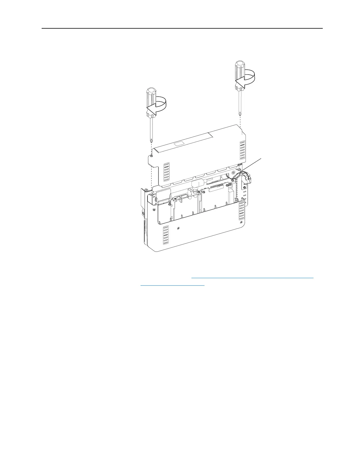
9. Install the outside front cover. The battery connectors should be kept
inside of the control assembly after the outside cover is installed.
10. Install the control assembly in the drive in reverse order of removal as
indicated in Step 3: Removing the 700S Phase II Control Assembly
from the Drive on page 4.
Proper tightening torque
for reassembly is 6 lb.-in
(0.7 N-m).
Keep connectors
inside covers
 Loading...


