MagneMover LITE User Manual Addendum,
Wide Vehicles
MMI-UM034B-EN-P Page 22 of 31
• Clearance Distance – The location, in meters, to the center of the vehicle where the
trailing edge of the vehicle is considered cleared from the node. Applies to the trailing
edge of all vehicles as they exit the switch, regardless of vehicle direction. The default is
0.0 (no clearance distance, see Node Clearance Distances and Entry Gate Positions on
page 27).
The vehicle size that is configured on the Motor Defaults page is used to update this
value automatically once a Path is selected.
• Entry Gate ID – A Configurator specified unique ID number for each Entry Gate.
• Entry Gate Distance – The location, in meters, to the center of the vehicle where the
leading edge of the vehicle is considered clear of vehicles and their payloads on adjoining
paths. Applies to all vehicles as they enter the switch regardless of vehicle direction. The
default is 0.0 (no entry gate, see Node Clearance Distances and Entry Gate Positions on
page 27).
The Configurator uses the vehicle size that is defined on the Motor Defaults page to
update this value automatically once a Path is selected.
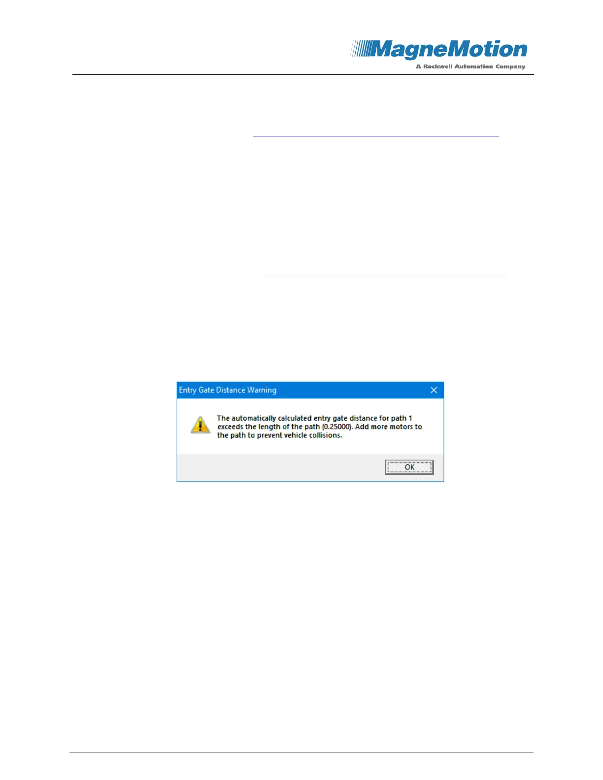
NOTE: If the Entry Gate position that is calculated by the Configurator is further from
the node than the length of the path, a warning similar to the one shown in
Figure 24 is displayed.
Figure 24: Entry Gate Distance Warning
• Consecutive Vehicle Limit – This limit applies to upstream motion through the switch.
For each exit path, this limit defines the number of vehicles that are allowed to traverse
the path upstream when there is a vehicle in cue for switch access in the upstream
direction on the other exit path. Once the specified number of vehicles has traversed the
switch or there are no more vehicles cued, additional vehicles on that exit path are
stopped and control of the switch is transferred to the other exit path. Any vehicles in cue
on that other exit path can then enter the switch (up the maximum that is specified for
that path if vehicles are now cued on the other path). The default is 0 (no limit).
 Loading...


