MagneMover LITE User Manual Addendum,
Wide Vehicles
MMI-UM034B-EN-P Page 28 of 31
MM LITE Switch
Diverge Node
Entry Gate ID 4
Path 1
Clearance Distance
Path 1
Entry Gate Distance
(Center of Puck)
Clearance Distance
(Center of Puck)
Entry Gate ID 5
Path 2
Clearance Distance
Path 2
Entry Gate ID 6
Path 3
Clearance Distance
Path 3
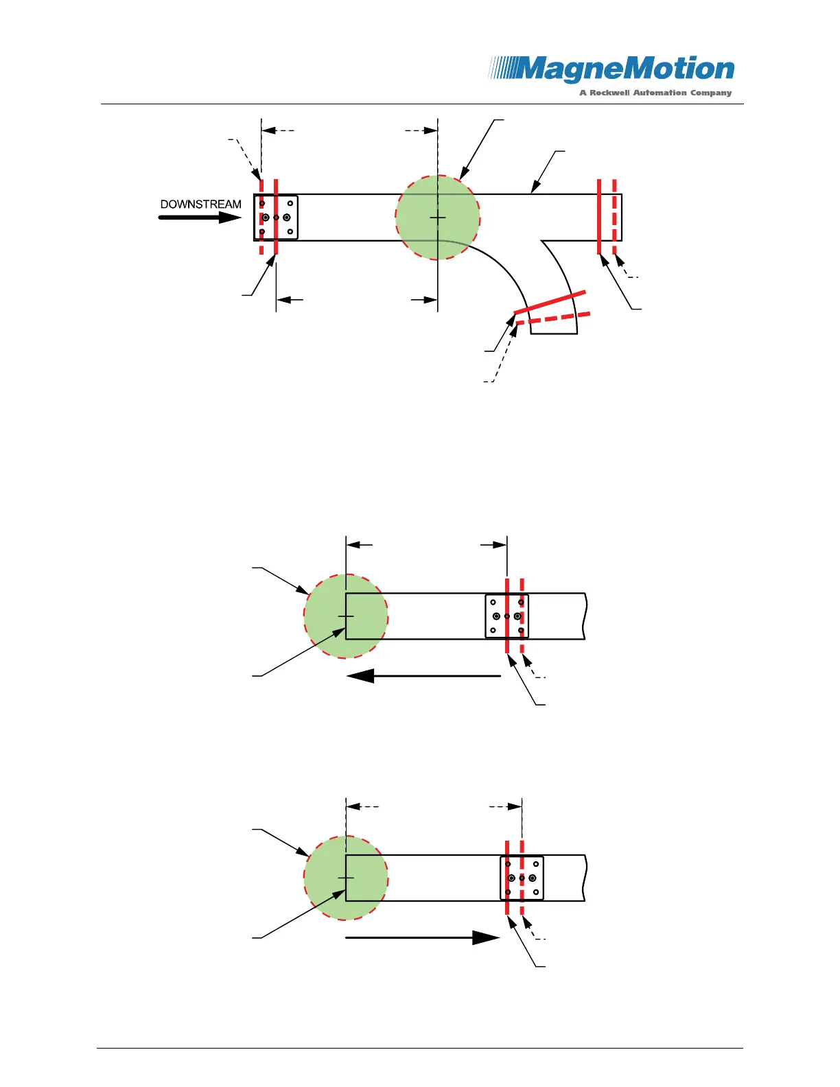
Figure 27: Node Clearance Distance and Entry Gate Position for Switch
All measurements for both Node Clearance Distances and Entry Gate positions on each path
are from the edge of the motor closest to the node to the center of the vehicle, as shown in
Figure 28 and Figure 29. The Configurator provides default values for both the Entry Gate
positions and the Node Clearance Distances.
Figure 28: Entry Gate Dimensions
Figure 29: Node Clearance Distance Dimensions
Motor
Clearance Distance
Entry Gate
Node
Entry Gate Distance
(Center of Puck)
Direction of Motion
Clearance Distance
Entry Gate
Motor
Node
Clearance Distance
(Center of Puck)
Direction of Motion
 Loading...


