MagneMover LITE User Manual Addendum,
Wide Vehicles
MMI-UM034B-EN-P Page 8 of 31
Supported and Unsupported Layouts
The MM LITE transport system now has limited knowledge of the track geometry in specific
cases, as described here and shown in the following examples.
• Vehicles clear the permission area of a motor while the center of the next vehicle is
over a motor that is not more than two motors distant along a vehicle route.
• A vehicle with its center on a motor cannot physically interfere with a vehicle with
movement permission on another motor two or fewer sequential motors away.
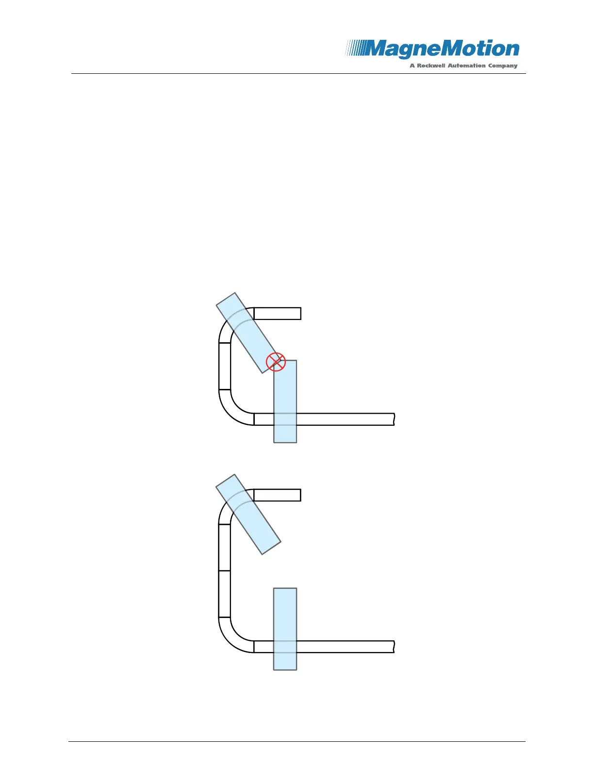
Figure 2 shows an example where a longer straight section is required between the curves
due to vehicle-to-vehicle interference. This interference includes the interference due to puck
rotation within the constraints of the rails (since the puck is not perfectly constrained as
shown in Figure 11). By adding a second motor between the curves, as shown in Figure 3,
this layout creates an allowed track topology with no vehicle-to-vehicle interference.
Figure 2: Interference of Vehicles More Than Two Motors Apart
Figure 3: Interference of Vehicles More Than Two Motors Apart Corrected
Once a vehicle gets beyond a certain size, straight motors must be inserted between any two
curves as shown in Figure 2 and Figure 3. The length of the straight motors that are required
 Loading...


