INSPECTING
AND
REPLACING
COUPLING
AND
SPIDER
ON
MOTOR
AND
SPINDLE
ASSEMIL
Y
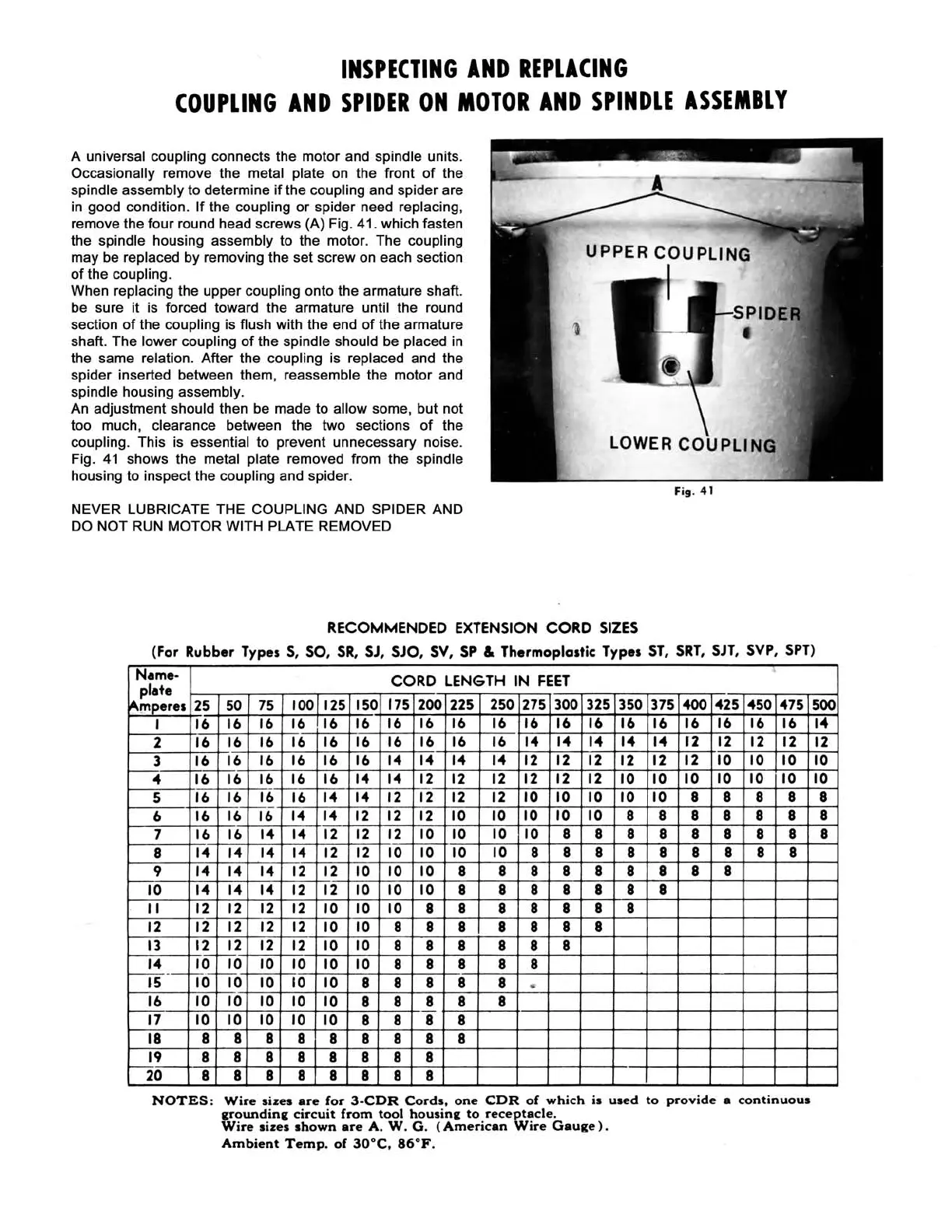
A universal coupling connects the motor and spindle units.
Occasionally remove the metal plate on the front
of
the
spindle assembly to determine
if
the coupling and spider are
in good condition.
If
the coupling
or
spider need replacing,
remove the
four
round head screws (A) Fig. 41. which fasten
the spindle housing assembly to the motor. The coupling
may be replaced by removing the set screw on each section
of
the coupling.
When replacing the upper coupling onto the armature shaft.
be sure it is forced toward the armature until the round
section
of
the coupling is flush with the end
of
the armature
shaft. The lower coupling
of
the spindle should be placed in
the same relation.
After
the coupling is replaced and the
spider inserted between them, reassemble the motor and
spindle housing assembly.
An adjustment should then be made to allow some, but not
too much, clearance between the two sections
of
the
coupling. This is essential to prevent unnecessary noise.
Fig.
41
shows the metal plate removed from the spindle
housing to inspect the coupling and spider.
NEVER LUBRICATE THE COUPLING AND SPIDER AND
DO NOT RUN MOTOR WITH PLATE REMOVED
LOWER
COUPLING
Fig. 41
RECOMMENDED EXTENSION
CORD
SIZES
(For
Rubber
Types 5, SO, 5R,
5J,
5JO,
SV, SP & Thermoplastic Types
ST,
5RT,
SJT, SVP, 5PT)
Name-
CORD
LENGTH
IN
FEET
•
plate
~rnp_eres
25
50
75
100
125
150
175
200 225
250 275
300
325
350
375
400
.25
.50
.75
I
16
16
16 16 16
16
16
16 16
16 16 16 16
16 16
16
16 16
16
2
16
16 16
16
16
16 16
16
16 16
I.
I.
I.
I.
I.
r2
12
12
12
3
16
16
16
16 16
16
I.
I. I. I.
12 12
12
12 12
12
10 10 10
•
16 16
16
16 16
I.
I.
12 12 12
12
12
12
10 10
10
10
10 10
5
16
16
16
16
I.
I.
12 12 12
12
10
10
10 10 10
8 8 8 8
6
16
16
16
I. I.
12 12
12
10
10
10 10
10
8 8 8 8 8 8
7
16 16
I.
I.
12
12
12
10 10
10
10
8 8 8 8 8 8
8
8
8
I.
I.
I.
I.
12
12
10
10
10
10
8
8
8 8 8 8 8 8 8
9
I.
I. I.
12
12
10
10 10
8 8 8
8 8
8 8
8 8
10
I.
I. I.
12
12 10
10
10
8 8 8 8 8 8 8
"
12 12 12
12
10 10
10
8
8
8
8 8 8 8
12
12
12 12 12
10
10
8
8 8 8 8
8 8
13
12
12 12
12
10 10
8 8 8 8 8 8
I.
10
10
10 10
10
10
8
8 8 8 8
r---rs
.-
10-
~O
10
10
10
8 8
8 8
8
..
16
10 10
10 10
10
8 8
8 8 8
17
10
10 10 10
10
8
8 8 8
18
8 8 8
8 8
8 8 8 8
19
8 8 8 8
8
8 8
8
20
8 8
8 8 8
8 8
8
NOTES:
Wire
sizes
are
for
3-CDR
Cords.
one
CDR
of
which
is
used
to
provide
a
continuous
grounding
circuit
from
tool
housing
to
receptacle.
Wire
sizes
shown
are
A.
W.
G.
(American
Wire
Gauge).
Ambient
Temp.
of
30°C.
86°F.
500
I.
12
10
10
8
8
8
 Loading...