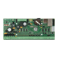
MC16 Operating Manual 09.01.2020
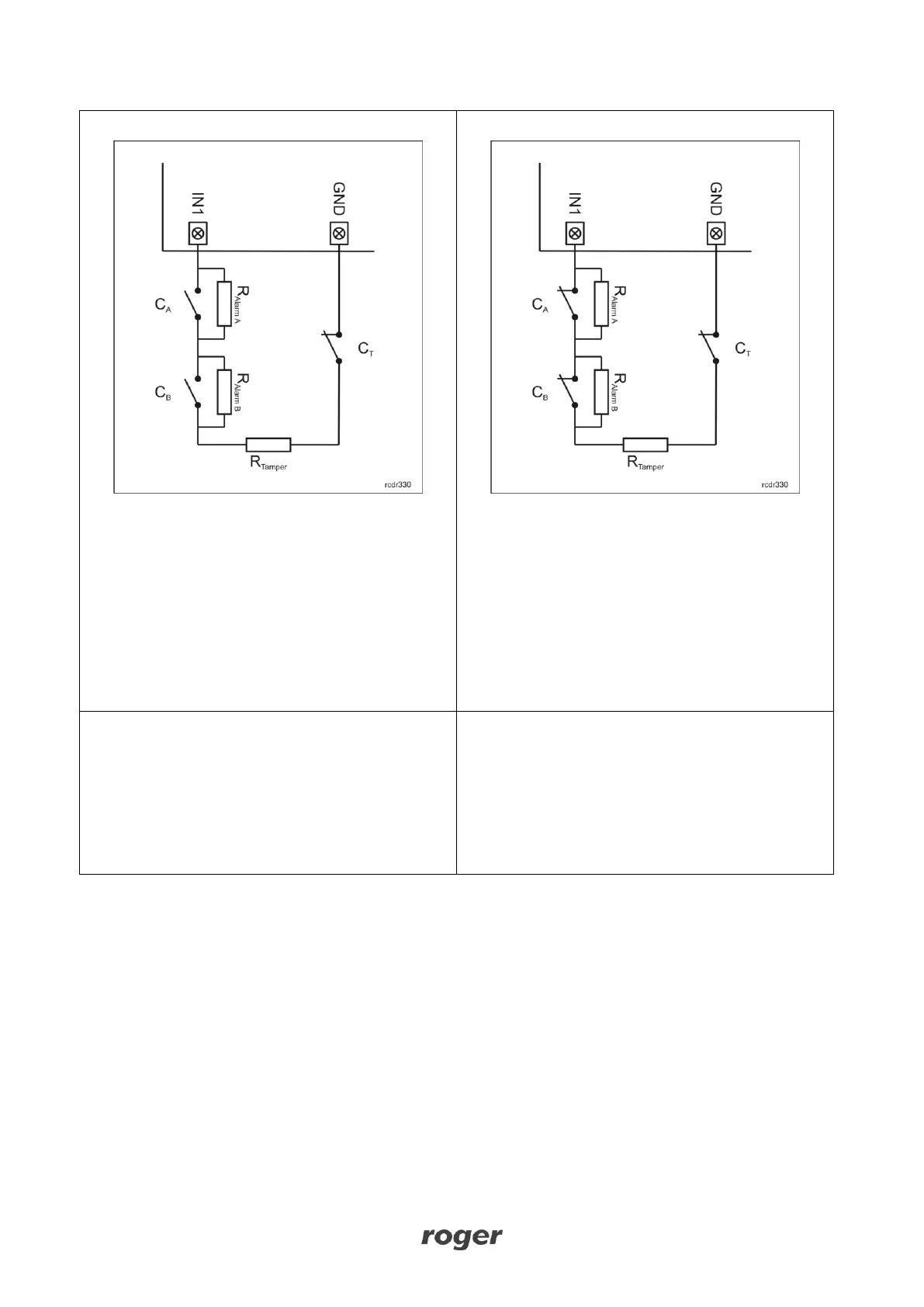
3EOL/NO input can be in normal, triggered,
masking, triggered with masking, tamper (sabotage)
or malfunction state. In normal state C
A
and C
B
contacts are opened while C
T
contacts are closed.
Input triggering is caused by C
A
contacts closing. C
B
contacts closing is recognized as the masking state.
Simultaneous closing of C
A
and C
B
contacts is
recognized as the triggered with masking state. C
T
contacts opening is recognized as the tamper
(sabotage) state. Input shorting to the ground is
recognized as the malfunction state.
3EOL/NC input can be in normal, triggered,
masking, triggered with masking, tamper (sabotage)
or malfunction state. In normal state C
A
, C
B
and C
T
contacts are closed. Input triggering is caused by C
A
contacts opening. C
B
contacts opening is
recognized as the masking state. Simultaneous
opening of C
A
and C
B
contacts is recognized as the
triggered with masking state. C
T
contacts opening is
recognized as the tamper (sabotage) state. Input
shorting to the ground is recognized as the
malfunction state.
3EOL/DW/NO input
3EOL/DW/NO input is operated in the same way as
3EOL/NO input with the exception that masking
state i.e. C
B
closing is interpreted as triggering of the
second input. In VISO software DW input type is
represented by two independent inputs. Each can
be used for different purpose and assigned with
different function.
3EOL/DW/NC input
3EOL/DW/NC input is operated in the same way as
3EOL/NC input with the exception that masking
state i.e. C
B
opening is interpreted as triggering of
the second input. In VISO software DW input type is
represented by two independent inputs. Each can
be used for different purpose and assigned with
different function.
Parametric resistors
The same values of parametric resistors are used for all inputs i.e. 1kΩ; 1,2kΩ; 1,5kΩ; 1,8kΩ; 2,2kΩ; 2,7kΩ;
3,3kΩ; 3,9kΩ; 4,7kΩ; 5,6kΩ; 6,8kΩ; 8,2kΩ; 10kΩ; 12kΩ. Tamper resistor defines a value of resistor used to
detect the tamper (sabotage) state. Alarm A resistor defines a value of resistor used to detect triggered
state. Alarm B resistor defines a value of resistor used to detect an additional triggering state of 3EOL/DW
input type or masking state of 3EOL input type. Alarm A resistor value must differ from value of Alarm B
resistor at least by three positions in the list above. Total resistance of wire used to connect contacts to input
should not exceed 100 Ω. Default values of parametric resistors:
Tamper = 1 kΩ
Alarm A = 2,2 kΩ
Alarm B = 5,6 kΩ
Response time
Response time parameter defines minimal impulse time on the input which triggers the input. Each input can
be configured individually in range of 50 to 5000 ms within low level configuration (RogerVDM).